WW AOG — Worldwide Aviation Operations GroupView course & enroll ↗
KA200-024 · King Air 200/B200

King Air 200/B200 Electrical Power, Batteries and Generator Diagnostics

Trace King Air 200/B200 battery power, starter-generators, generator control units (GCUs), line contactors, dual-fed distribution loops and instrument supplies. Four identified installed profiles, a 38-page handbook and six interactive visual workshops connect ten lesson decisions, ten paired fault cases and three independent five-field jobs. Includes a separate 40-question final at 80%.

Self-paced onlineWWAOG Technical Academy
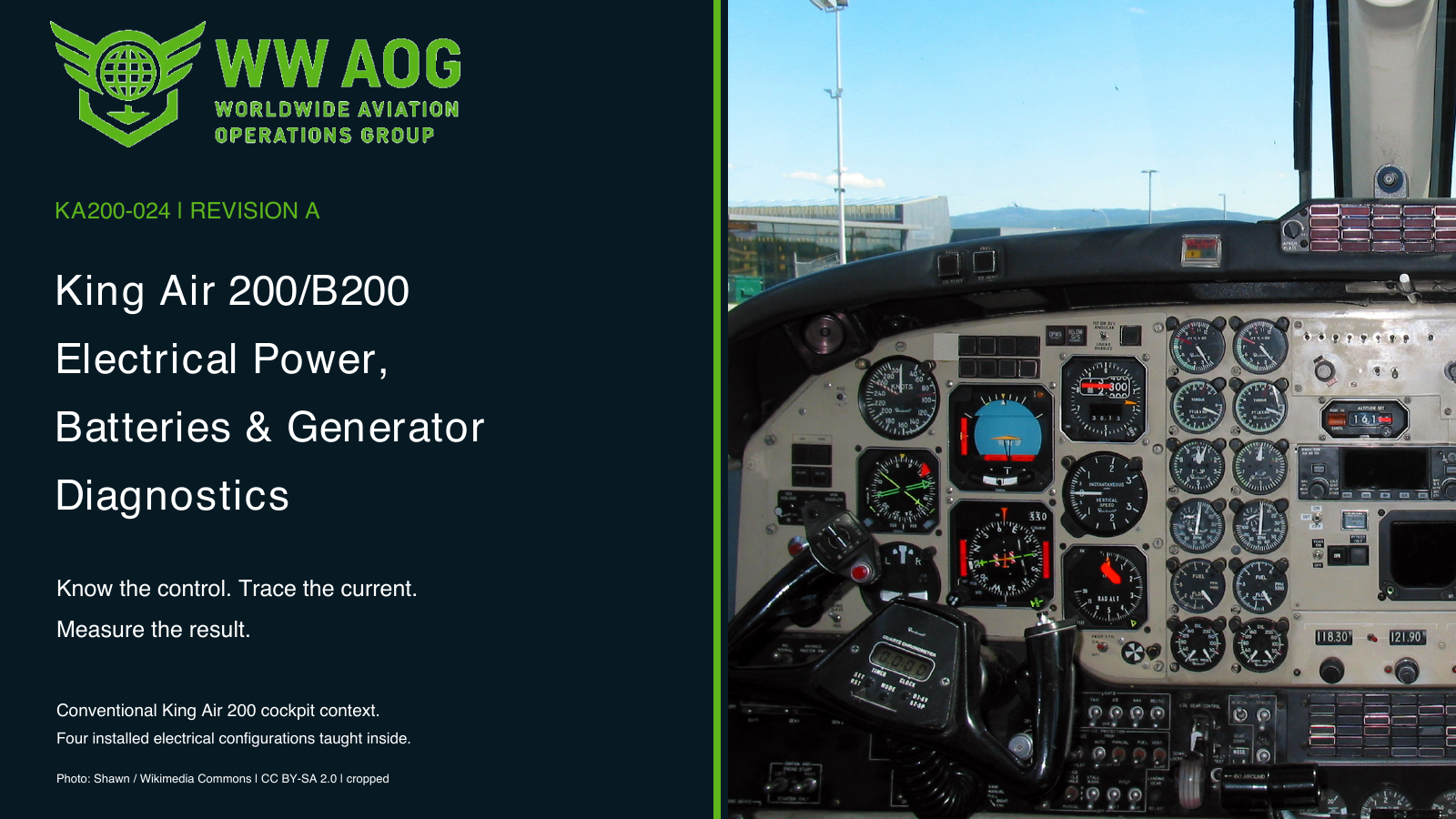
King Air 200/B200 Electrical Power, Batteries and Generator Diagnostics course cover

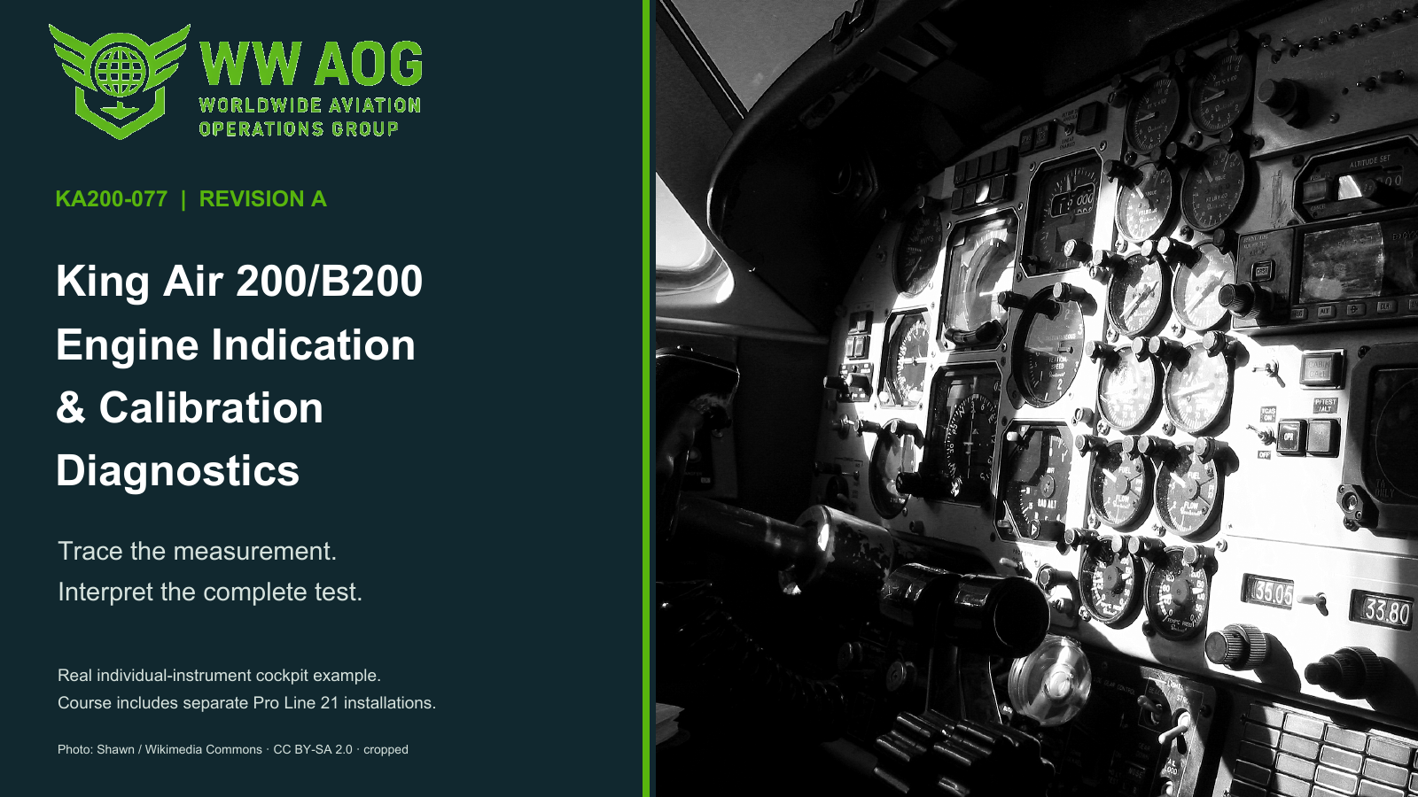
Photo: Shawn. Conventional King Air 200 cockpit context; each assessed electrical configuration is identified separately. View photograph source · CC BY-SA 2.0. Cropped from the original photograph; registration placard is outside the crop. No instrument geometry altered or photographed gauge value used as a maintenance acceptance measurement.

Inside KA200-024

What you will study

Battery power and distribution

Locate the right-wing battery, battery relay, hot bus, A145 DC distribution panel and later GCUs immediately aft of A145. Follow current limiters and paired isolation diodes through the four dual-fed distribution loops, then connect actual master/relay state to the powered load.

Generation, regulation and load sharing

Separate generated voltage from line-contactor closure and load carried. Compare named generator-terminal and GCU sensing measurements before adjustment, then use the correct early-rheostat or later-GCU screw direction and repeat checks. Keep the original Leland load-sharing task separate from the later GCU regulated-voltage band of 28.00–28.50 V.

Battery health and external power

Calculate delivered ampere-hours and compare the separate endpoint-voltage requirement. Distinguish Ni-Cd charge-current indication, sealed lead-acid reserve testing, GPU indication, relay enabling and measured bus voltage.

Instrument AC and later DC supplies

Check the separate 115 V, frequency and 26 V inverter outputs in the retained-inverter profiles. Follow RR-18 No.1 to pilot PFD/AHC1 and No.2 to MFD/AHC2 in the identified later DC-avionics profile.

Learning outcomes

  • Select among four confirmed installed electrical profiles using aircraft and equipment records.
  • Trace battery, hot-bus and switched-distribution power without confusing a switch command with physical isolation.
  • Distinguish failed generation, an open output connection and an indicated load discrepancy.
  • Identify voltage-sensing drops before selecting a regulator adjustment.
  • Choose the actual clockwise/increase or counterclockwise/decrease GCU direction and verify fresh measurements.
  • Interpret dual-feed loop continuity and unintended connections between numbered loops.
  • Calculate battery reserve and shunt-scale results while retaining their separate acceptance criteria.
  • Compare each required inverter output and identify the later RR-18 DC-avionics relationships.
  • Complete restoration and repeated measurements in an electrical maintenance training record.

Aircraft and course applicability

Training based on supplied King Air 200/B200 Maintenance Manual 101-590010-19 Chapter 24, whose effective-page list is dated November 1, 2024 with mixed task dates. Four identified BB-series study profiles distinguish original Leland BB70, later GCU/Ni-Cd BB1200, GCU/sealed lead-acid BB1750 and Pro Line 21 DC-avionics BB1900 installations. Select the actual aircraft serial, installed equipment and modification record before applying a task. B200GT/PT6A-52, Fusion and BL/BN/BT/BY configurations are outside these four assessed profiles. Aircraft work uses complete current applicable maintenance instructions.

WWAOG provides independent training. Online completion records knowledge and simulation achievement; it does not replace observed practical qualification, employer authorization or applicable licensing. Use current aircraft-effective maintenance instructions for physical work.
Before you enroll

Is this course suitable for my aircraft or role?

Training based on supplied King Air 200/B200 Maintenance Manual 101-590010-19 Chapter 24, whose effective-page list is dated November 1, 2024 with mixed task dates. Four identified BB-series study profiles distinguish original Leland BB70, later GCU/Ni-Cd BB1200, GCU/sealed lead-acid BB1750 and Pro Line 21 DC-avionics BB1900 installations. Select the actual aircraft serial, installed equipment and modification record before applying a task. B200GT/PT6A-52, Fusion and BL/BN/BT/BY configurations are outside these four assessed profiles. Aircraft work uses complete current applicable maintenance instructions. If you are choosing training for a different installation or a team, email info@wwaog.com with your aircraft configuration, learner experience and training goals.

Where do I find the price and sign up?

Open the KA200-024 enrollment page for the current price, course contents and signup options. Enrollment takes place in WWAOG Academy, where learners access their assigned content.

Can WWAOG train our team at our location?

Yes. Tailored on-site training is available by separate arrangement. Describe your aircraft, location, team size and learning objectives so WWAOG can propose an appropriate scope.

Free course sample · KA200-024

Learn the relationship. Test your reasoning.

Try a short teaching exercise from the subject of King Air 200/B200 Electrical Power, Batteries and Generator Diagnostics. No account needed.

About 2 minutes
01 · Understand

The generator control unit (GCU) regulates the generator field using its voltage-sensing input. Generator output terminal B and that GCU input should represent the same generator voltage. A resistive connection between them can make the controller regulate against the wrong value.

Simplified system relationship
  1. Generator output terminal B
  2. Generator-voltage sensing connection
  3. GCU generator-voltage input
02 · Read the supplied record

During a qualified later-GCU load-sharing check, the left generator carries excessive load. Same verified ground: its terminal B is 29.70 V and its GCU generator-voltage input is 27.70 V. These supplied measurements use identified test points and the same verified ground. They are not an instruction to probe an unidentified connector.

03 · Make a decisionWhich left generator circuit should be checked first to explain the 2.00 V difference between terminal B and the GCU voltage-sensing input?

Original public teaching example based on the course’s published scope. Supplied records and values are training data. Aircraft maintenance uses current applicable instructions; this sample does not record course completion.

Explore more free course samplesReview KA200-024 and enroll ↗

Regional standards and support

Our aircraft systems courses use manufacturer technical manuals to support pilots and maintenance personnel working in FAA- and EASA-regulated aviation. Training combines detailed system explanations, knowledge checks and interactive exercises for initial familiarization and recurrent study.

Training at your location

Your aircraft. Your team. A course built around both.

WWAOG offers tailored on-site courses for operators, maintenance organizations and government teams. We can shape the course around your aircraft configuration, installed systems, technician experience and operational training goals.

Tell us what your team needs

  • Aircraft model and equipment configuration
  • Location, group size and technician experience
  • System topics and desired learning outcomes
  • Preferred dates and available training resources

We’ll agree the scope, delivery plan and quotation before scheduling. Tailored on-site training is arranged separately from individual online course enrollment.

Request tailored on-site training
KA200-024 · Self-paced learning

Build knowledge you can apply to better maintenance decisions.