What you will study
Turn the released drawing and BOM into a complete job
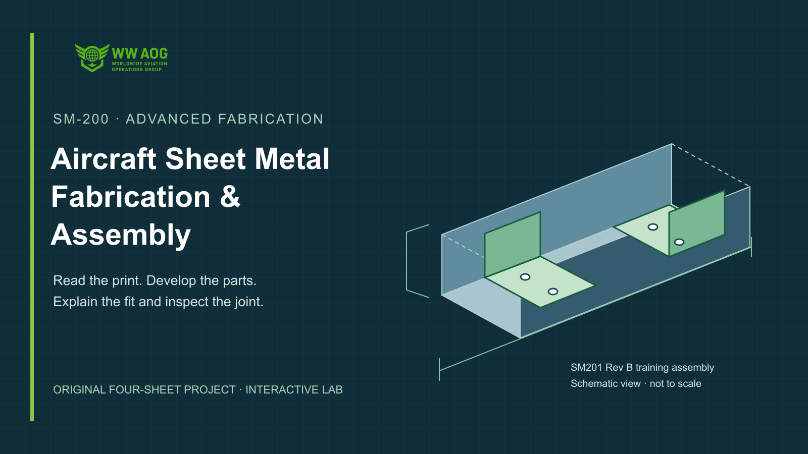
Work from the correct SM201 Rev B assembly, detail and process-card sheets. Relate item numbers, part identity, datum, local tolerances, material and grain direction to a complete blank takeoff that includes cutting trim and kerf.
Develop the channel and clips from their own forming inputs
Calculate both bend zones of the channel and develop the separately formed clips from their distinct PC201 process inputs. Connect inside radius, material thickness, stated neutral-axis factor and bend angle to the flat layout, relief geometry and actual forming-tool access.
Check flat-bearing clearance and the tolerance budget
Distinguish clearance between the channel walls from usable flat-bearing clearance beside the bend. Calculate the worst-case tolerance budget and compare actual dimensions without rounding a failed result into acceptance.
Inspect holes, fasteners and the finished stack
Treat finished-hole size, position, edge distance and pitch as separate requirements. Interpret the specified solid-rivet identity, measured stack and preliminary projection, then compare the named blind-rivet and pin/collar coding examples within their own family rules.
Demonstrate a traceable fabrication decision
Use seven interactive calculation and inspection views, eight lesson checks, six prediction-and-Apply exercises, eight two-stage coached jobs and six fixed records with 18 classifications and six entered calculations. Complete all 24 lab requirements; the 12-question independent review requires at least 80% and all eight critical decisions correct in one attempt. Pass the separate 32-question final with at least 26 correct. Practical fabrication qualification remains separate.
Learning outcomes
- Read a complete assembly/BOM/detail/process-card set using the correct revision, datum and specific tolerance.
- Develop a two-bend channel and a separately formed clip using their distinct stated process inputs.
- Plan complete blanks with grain, cutting trim and kerf; identify the required relief and forming access.
- Calculate the actual flat-bearing clearance and worst-case tolerance budget without rounding a failed value into acceptance.
- Compare finished-hole size, location, edge distance and pitch as separate requirements.
- Interpret full solid-rivet identity, measured stack and preliminary projection; distinguish named blind-rivet and pin/collar coding examples.
- Build a traceable fabrication handoff retaining original findings, authorized disposition and fresh affected inspection.
Aircraft and course applicability
Applied fabrication planning and supplied-evidence interpretation for the original WWAOG SM201 Rev B two-bend channel and two mating clips. The four-sheet drawing/BOM/detail/process-card kit and all numerical forming inputs, dimensions and acceptance examples apply only to this fictional, nonserviceable training assembly. FAA, identified Cessna SRM, CherryLOCK and named Hi-Lok-family sources support the stated practices and coding examples; they do not establish an aircraft repair design, load rating, universal forming factor or fastener substitution. Actual aircraft work requires its current applicable drawing, SRM and supplier instructions, supervised hands-on skill development and required authorization.
WWAOG provides independent training. Online completion records knowledge and simulation achievement; it does not replace observed practical qualification, employer authorization or applicable licensing. Use current aircraft-effective maintenance instructions for physical work.