What you will study
Establish the right dry-rig reference
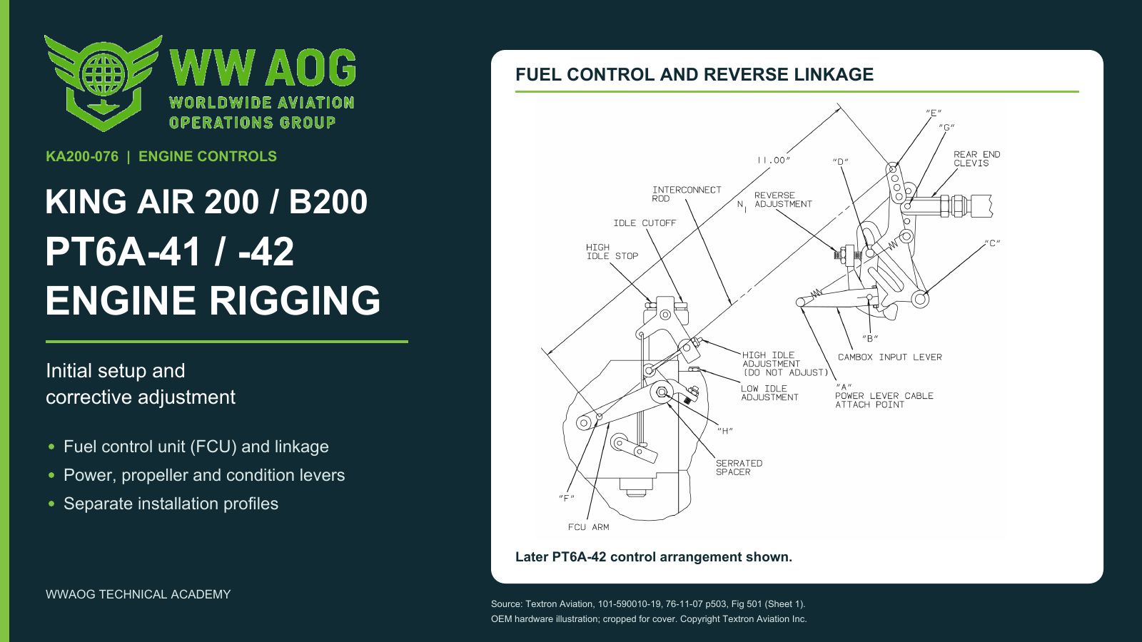
Identify the FCU arm, cambox, interconnect rod and attachment holes before setting the linkage. Compare the earlier FCU-arm reference with the later A-B-C cambox alignment, then connect condition-control cutoff and propeller cable travel to their separate checks.
Correct the named fault and measure again
Recognize a constant knob split versus one that grows through the power range. Select the affected engine’s rod or FCU arm in the stated viewing face, then compare new paired-engine readings. Keep idle, governor settings, flight-idle torque, beta movement and reverse N1 with their own criteria.
Track the joint through the adjustment
Use the shared-linkage guide to record witness marks, identify intended movement, check spring response separately, restore the correct attachment and repeat the affected dry and running checks.
Follow the selected installation through completion
Select the earlier PT6A-41, earlier PT6A-42 or later four-blade PT6A-42 record. The course contains ten lesson decisions, ten paired cases and four five-field jobs; each profile requires only its applicable activities, with progress saved separately. Complete those activities and the separate 40-question combined final at 80% (32 correct). Visual exploration and the shared-linkage guide are ungraded.
Learning outcomes
- Trace power, propeller and condition-lever movement through the named cables, rods and engine-mounted controls.
- Select the documented installed-control branch and explain its initial geometry and endpoint checks.
- Distinguish constant from progressive power-lever stagger and identify the named engine, adjustment part and direction.
- Interpret cutoff, idle, governing, flight-idle torque, beta and reverse results without mixing test conditions or units.
- Build a clear before/after record with secured hardware, fresh measurements and affected checks repeated.
Aircraft and course applicability
For the identified King Air 200/B200 PT6A-41 and PT6A-42 external engine-control installations in Maintenance Manual 101-590010-19 Chapters 61, 71, 76 and 77, supplied effective-page list November 1, 2024. Engine model, propeller and installed control mechanism select the task. Covers external control rigging after engine-installation acceptance and in-service corrections. Internal FCU and governor overhaul or calibration are separate tasks. Aircraft work requires current applicable instructions and qualified personnel; online completion does not establish observed practical rigging competence or maintenance-release authority.
WWAOG provides independent training. Online completion records knowledge and simulation achievement; it does not replace observed practical qualification, employer authorization or applicable licensing. Use current aircraft-effective maintenance instructions for physical work.