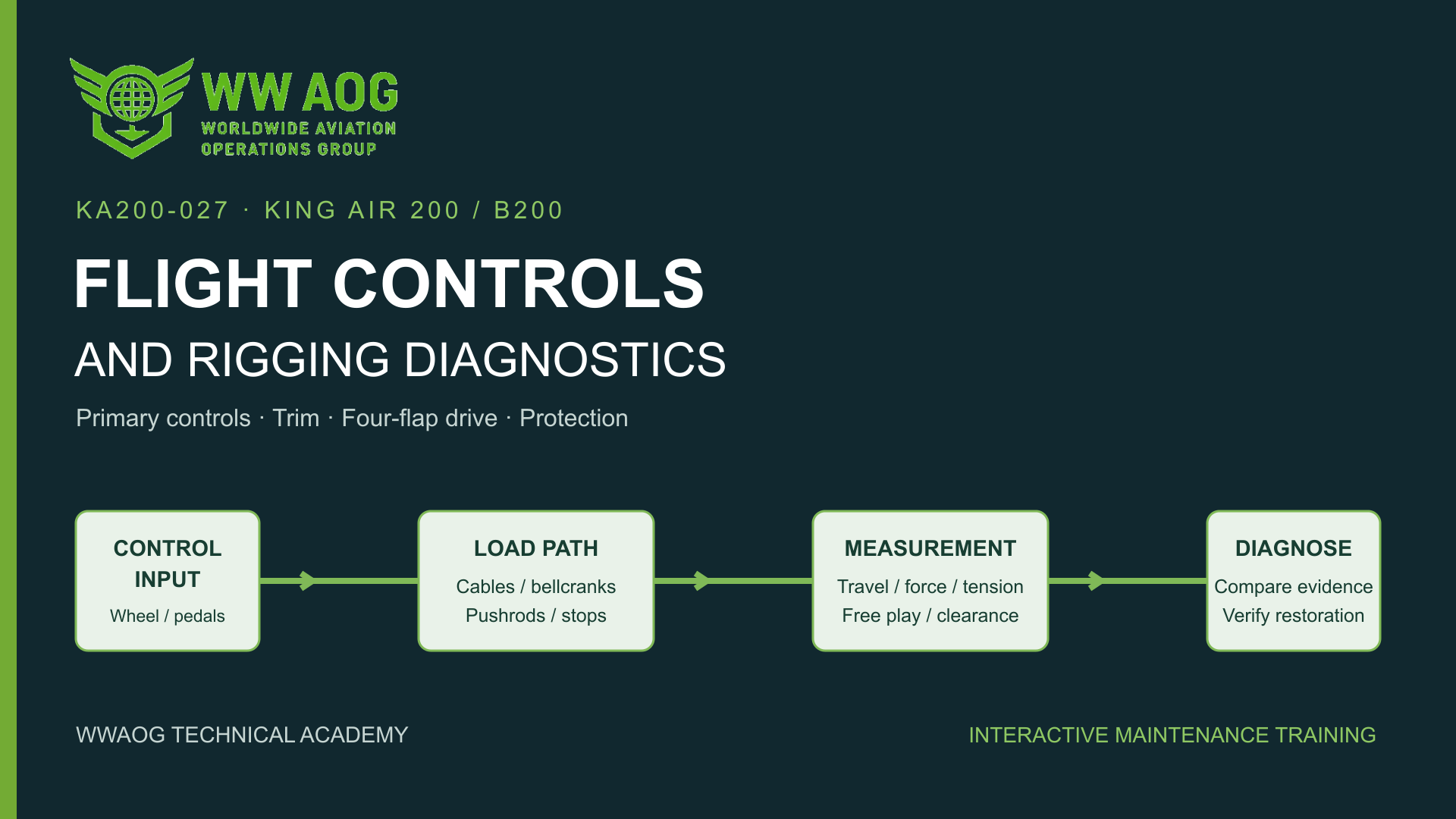
King Air 200/B200 Flight Controls and Rigging Diagnostics
Trace manual aileron, elevator and rudder controls, separate trim drives, conventional rudder assistance and the four-flap protection system. A 39-page handbook and clickable visual workshop connect ten lesson decisions, ten paired fault cases and three independent five-field rigging jobs. Includes a separate 40-question final at 80%. Locate real control wheels, electric-trim switches, rudder trim and flap controls, then follow the normal mechanical roll-control flow.
Identify the control-wheel, pedal, quadrant, cable, bellcrank, pushrod and stop relationships before diagnosing the observed surface response.
Trim, assistance and powered functions
Separate actual tab geometry from indication, split-switch operation from electric-trim disconnect and clutch capability, and conventional rudder-boost pressure from mechanical servo-cable transfer.
Measured rigging comparisons
Interpret aileron endpoint/differential/force/lost motion, each tab free-play fixture, final elevator average and the distinct bobweight cushion/stop-clearance measurements.
Four-flap drive and protection
Trace the four shaft/actuator paths, right-inboard indication, serial/kit protection branch and Pro Line 21 direction-specific approach checks. Connect stall-warning flap and air/ground inputs to their named checks.
Learning outcomes
Choose the actual flight-control task from serial, modification and installed equipment records.
Trace a reported failure through its named mechanical, electrical or pneumatic component path.
Calculate and classify the stated angle, force, tension, clearance and four-load free-play results.
Separate a correct indication from actual four-flap synchronization and protection response.
Build a repeatable correction, restoration and measured retest record.
Aircraft and course applicability
Systems and maintenance-record training for the identified King Air 200/B200 branches of Maintenance Manual 101-590010-19 Chapter 27, supplied effective-page list November 1, 2024. Aircraft serial, S.I. 0960, installed bobweight/flap-safety kits and avionics configuration select the task. The study edition does not establish current aircraft applicability; physical rigging uses current controlled instructions, task equipment and qualified personnel.
WWAOG provides independent training. Online completion records knowledge and simulation achievement; it does not replace observed practical qualification, employer authorization or applicable licensing. Use current aircraft-effective maintenance instructions for physical work.
Before you enroll
Is this course suitable for my aircraft or role?
Systems and maintenance-record training for the identified King Air 200/B200 branches of Maintenance Manual 101-590010-19 Chapter 27, supplied effective-page list November 1, 2024. Aircraft serial, S.I. 0960, installed bobweight/flap-safety kits and avionics configuration select the task. The study edition does not establish current aircraft applicability; physical rigging uses current controlled instructions, task equipment and qualified personnel. If you are choosing training for a different installation or a team, email info@wwaog.com with your aircraft configuration, learner experience and training goals.
Where do I find the price and sign up?
Open the KA200-027 enrollment page for the current price, course contents and signup options. Enrollment takes place in WWAOG Academy, where learners access their assigned content.
Can WWAOG train our team at our location?
Yes. Tailored on-site training is available by separate arrangement. Describe your aircraft, location, team size and learning objectives so WWAOG can propose an appropriate scope.
KA200-027 · Start with the real cockpit
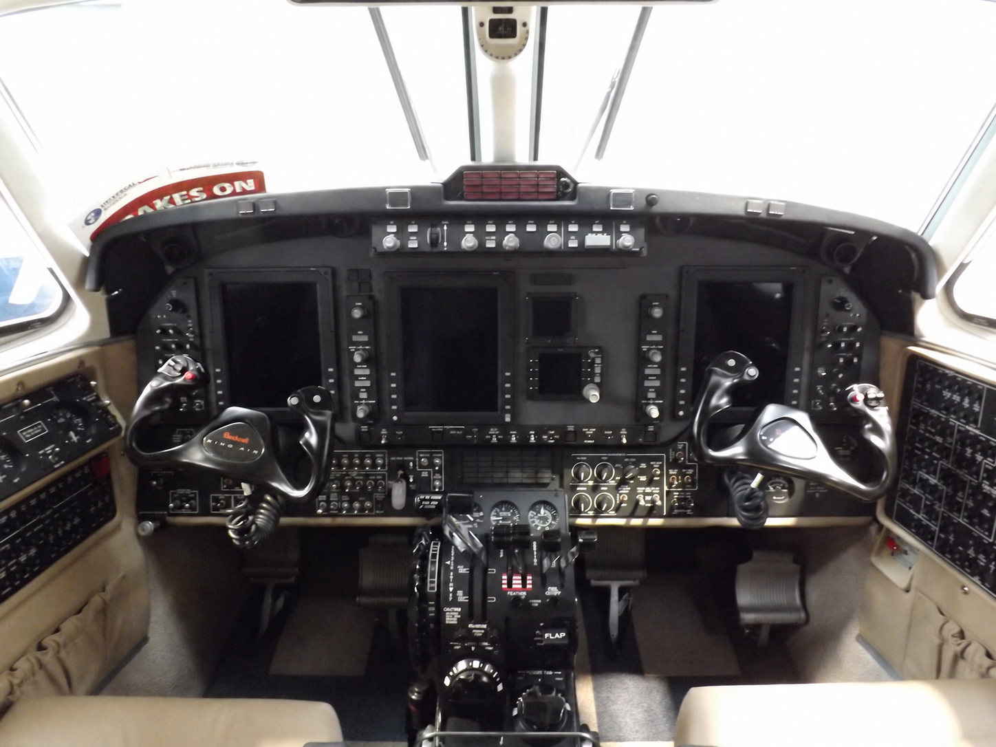
Find the flight controls, then follow what they move
A control wheel, a trim switch and a flap selector do different jobs. Find each visible control, read its normal purpose, then follow the named mechanical or electrical path before trying the course’s measured fault cases.
“Beech Super King Air B200GTI cockpit” by James, via Wikimedia Commons. CC BY-SA 2.0. Aircraft registration removed for privacy. Interactive labels by WWAOG. The photograph and labeled photo view are licensed under CC BY-SA 2.0; assessment text and the original system-flow diagram remain separate. No photographer or manufacturer endorsement is implied.
Find it in the photograph, then read its action, purpose and connection to the rest of the system. You can also choose a named item in the list. Keyboard users can use Tab and Enter or Space.
Normal roll-control path: from the wheel to the ailerons
Original simplified relationship diagram. It shows the normal manual roll-control path, not cable routing, dimensions, an autopilot schematic or a rigging procedure.
1
Control wheels
The pilot or copilot rotates a mechanically interconnected wheel.
2
Control-column chain and cables
Sprockets, chain and the column cable assembly carry wheel rotation into the aileron cable circuit.
3
Fuselage cables and aileron quadrant
The fuselage cable path moves the applicable quadrant or compensating-quadrant arrangement.
4
Wing cables and bellcranks
Cables in the wings carry the movement to the aileron bellcranks.
5
Push-pull rods and ailerons
The rods connect each bellcrank to its aileron, producing the corresponding surface movement.
Expected normal response: From the pilot seat, turning the wheel right raises the right aileron and lowers the left aileron. Turning the wheel left reverses those movements. The cable-and-linkage path transmits that roll command mechanically; it does not require the flap motor or electric trim. Use the applicable maintenance task for the actual direction, travel, friction and lost-motion checks.
Study reference: 101-590010-19, 27-00-00 p. 1; 27-10-03 pp. 401–403 Figure 401; 27-10-05 p. 501 and Figures 401/505. Use the installed quadrant branch. Normal roll direction: FAA Pilot’s Handbook of Aeronautical Knowledge, Flight Controls, p. 6-3 (actual PDF 153), https://www.faa.gov/sites/faa.gov/files/pilot_handbook_1.pdf.
The photograph source identifies this cockpit as a B200GTI. This is a cockpit-layout example, not proof of a 200/B200 serial, modification or installed-control branch. The photo does not supply a rigging result. Match the aircraft records and applicable Chapter 27 task before maintenance.
This guided photo activity explains the visible equipment. Selecting a label does not operate an aircraft control or record course completion. Continue with the system diagram and supplied fault record to practice troubleshooting.
Free course sample · KA200-027
Learn the relationship. Test your reasoning.
Try a short teaching exercise from the subject of King Air 200/B200 Flight Controls and Rigging Diagnostics. No account needed.
About 2 minutes
01 · Understand
One motor and gearbox drive four flexible shafts and jackscrew actuators. The cockpit potentiometer follows the right-inboard flap. The asymmetry mechanism compares the inboard/outboard pair on each wing and interrupts the common motor command at its installed rigged split. The cited trip-setting band is 3–6 degrees.
Compare physical flap phase, protection and indication
Four measured flap positions→
Same-wing asymmetry mechanism and common motor circuit→
Separate right-inboard potentiometer indication
02 · Read the supplied record
A fictional B200 with the later roller-switch protection installed has supplied measured angles: left outboard 12°, left inboard 12°, right inboard 12° and right outboard 4°. Its indicator agrees with right inboard at 12°. In the prescribed controlled test, the normally connected protection circuit still permits the common flap motor command at the recorded split.
Original public teaching example based on the course’s published scope. Supplied records and values are training data. Aircraft maintenance uses current applicable instructions; this sample does not record course completion.
Our aircraft systems courses use manufacturer technical manuals to support pilots and maintenance personnel working in FAA- and EASA-regulated aviation. Training combines detailed system explanations, knowledge checks and interactive exercises for initial familiarization and recurrent study.
Training at your location
Your aircraft. Your team. A course built around both.
WWAOG offers tailored on-site courses for operators, maintenance organizations and government teams. We can shape the course around your aircraft configuration, installed systems, technician experience and operational training goals.
Tell us what your team needs
Aircraft model and equipment configuration
Location, group size and technician experience
System topics and desired learning outcomes
Preferred dates and available training resources
We’ll agree the scope, delivery plan and quotation before scheduling. Tailored on-site training is arranged separately from individual online course enrollment.
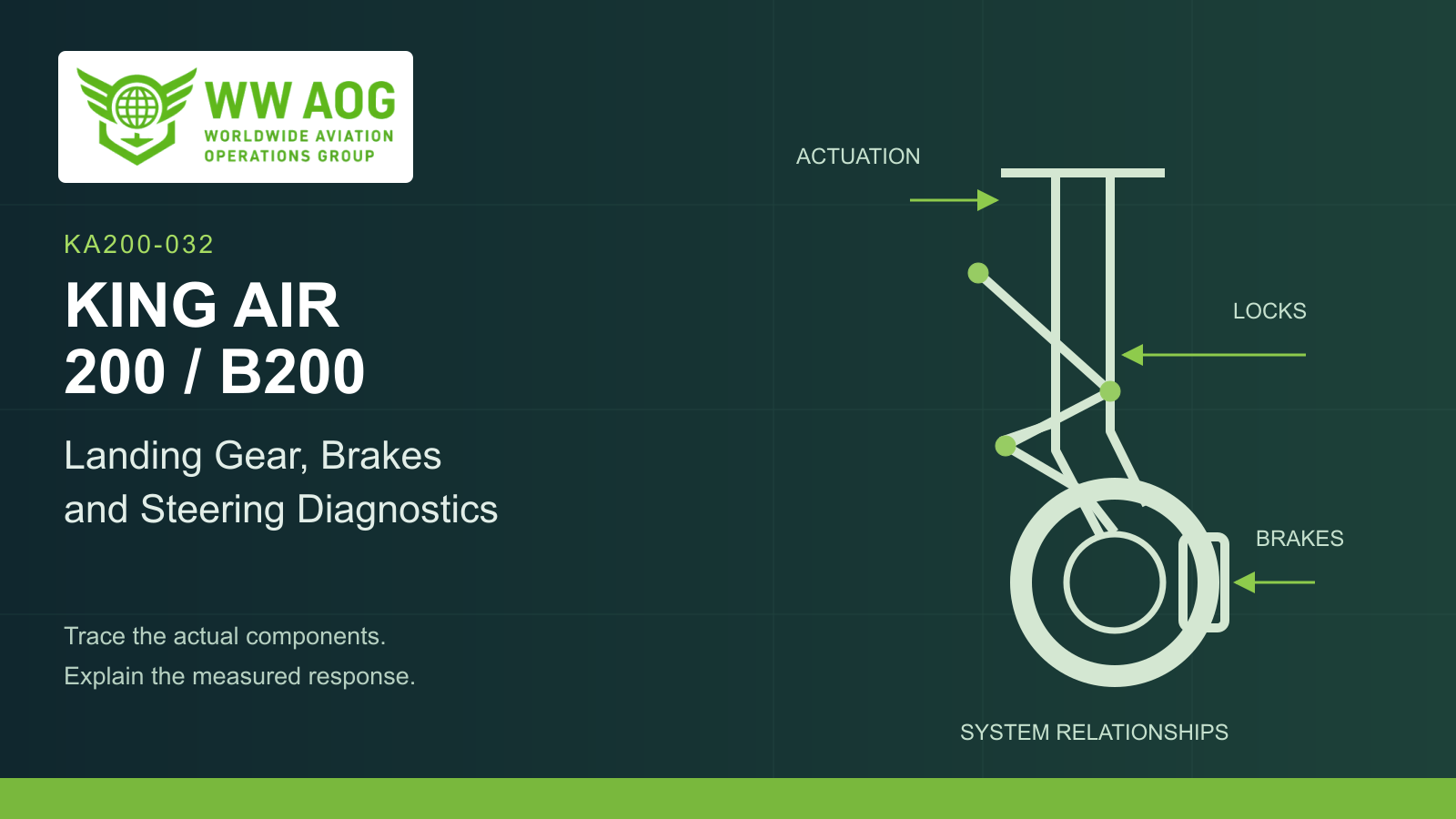
Trace the gear drive, identify the physical lock and compare the actual hydraulic, electrical or mechanical response. Learn why a passing lamp, switch or pressure test can leave the original fault unresolved. A 47-page handbook and clickable mechanical/hydraulic gear, brake and steering schematics connect ten lesson decisions, ten paired cases and three independent five-field jobs. Includes a separate 40-question final at 80%.
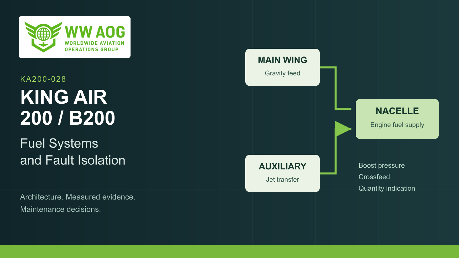
Trace main-wing gravity feed, auxiliary jet-pump transfer, standby boost and crossfeed using the actual King Air 200/B200 component names. A 35-page handbook, interactive fuel schematic, ten two-part fault cases and three measured work records connect system operation to a defensible diagnosis. Includes a separate 40-question final at 80%.
Read the applicable maintenance task, trace named circuits and identify complete parts rows. A 31-page illustrated handbook, nine lesson decisions, ten two-part practice cases and three document work orders connect aircraft effectivity, wiring sheets, connector views and IPC parts requests. Includes a separate 40-question final at 80%.