King Air 200/B200 Air Conditioning, Heating and Pressurization
Follow engine P3 bleed air through the flow-control units, wing heat exchangers and cabin ducts, then connect inflow, outflow-valve regulation and vapor-cycle cooling. A 46-page handbook, interactive system diagram, ten lesson decisions, twelve paired fault cases and a six-field maintenance job build configuration-specific fault isolation. Includes a separate 40-question final at 80%.
Identify the installed branch before choosing a task
Use aircraft serial, engine installation, FCU identification and modification records. Select pneumatic or electronic FCU tasks separately from classic or dual-zone cabin distribution; do not infer both from the model name.
Trace bleed air, cabin exhaust and control vacuum
Follow environmental bleed air through the FCU, wing heat exchanger or hot-air bypass, mixing assembly and cabin outlets. Distinguish inflow and leakage from outflow-valve regulation, and compare ground PRESS, prescribed TEST and flight control conditions.
Connect cabin cooling to the refrigerant circuit
Follow the right-engine-driven compressor, condenser, receiver/dryer, expansion valves and evaporators. Relate blower airflow, humidity, refrigerant behavior, sensing-bulb attachment and unwanted bleed heat to local and shared cooling complaints.
Turn observations into a useful maintenance record
Compare controller commands with ambient-valve shaft travel, use the correct temperature/flow sensor circuit and table, assess each pressure result under its own test method, and record restoration plus repeat checks for a fictional right-FCU job.
Learning outcomes
Select the applicable FCU, cabin-distribution, heating and cooling task branches from the supplied aircraft record.
Explain how P3 bleed air, heat exchangers, mixing assemblies and recirculated air produce cabin inflow and comfort.
Distinguish the cabin exhaust path from the vacuum controls and explain ground PRESS versus TEST/flight behavior.
Use component-specific observations to distinguish valve, controller, sensor, airflow and refrigeration faults.
Record the failed function, supported isolation, restored configuration and repeat-check evidence for an environmental-system job.
Aircraft and course applicability
Systems and maintenance-decision training for the named King Air 200/B200 configurations in supplied Maintenance Manual 101-590010-19 Chapter 21, with its November 1, 2024 effective-page list. Classic and dual-zone distribution, pneumatic and electronic FCUs, and installed heating/cooling options have separate applicability. This study edition does not establish current aircraft applicability; actual work requires current applicable controlled instructions and the aircraft configuration record.
WWAOG provides independent training. Online completion records knowledge and simulation achievement; it does not replace observed practical qualification, employer authorization or applicable licensing. Use current aircraft-effective maintenance instructions for physical work.
Before you enroll
Is this course suitable for my aircraft or role?
Systems and maintenance-decision training for the named King Air 200/B200 configurations in supplied Maintenance Manual 101-590010-19 Chapter 21, with its November 1, 2024 effective-page list. Classic and dual-zone distribution, pneumatic and electronic FCUs, and installed heating/cooling options have separate applicability. This study edition does not establish current aircraft applicability; actual work requires current applicable controlled instructions and the aircraft configuration record. If you are choosing training for a different installation or a team, email info@wwaog.com with your aircraft configuration, learner experience and training goals.
Where do I find the price and sign up?
Open the KA200-021 enrollment page for the current price, course contents and signup options. Enrollment takes place in WWAOG Academy, where learners access their assigned content.
Can WWAOG train our team at our location?
Yes. Tailored on-site training is available by separate arrangement. Describe your aircraft, location, team size and learning objectives so WWAOG can propose an appropriate scope.
KA200-021 · Start with the real cockpit
Find the environmental controls, then trace heat, cooling and cabin pressure
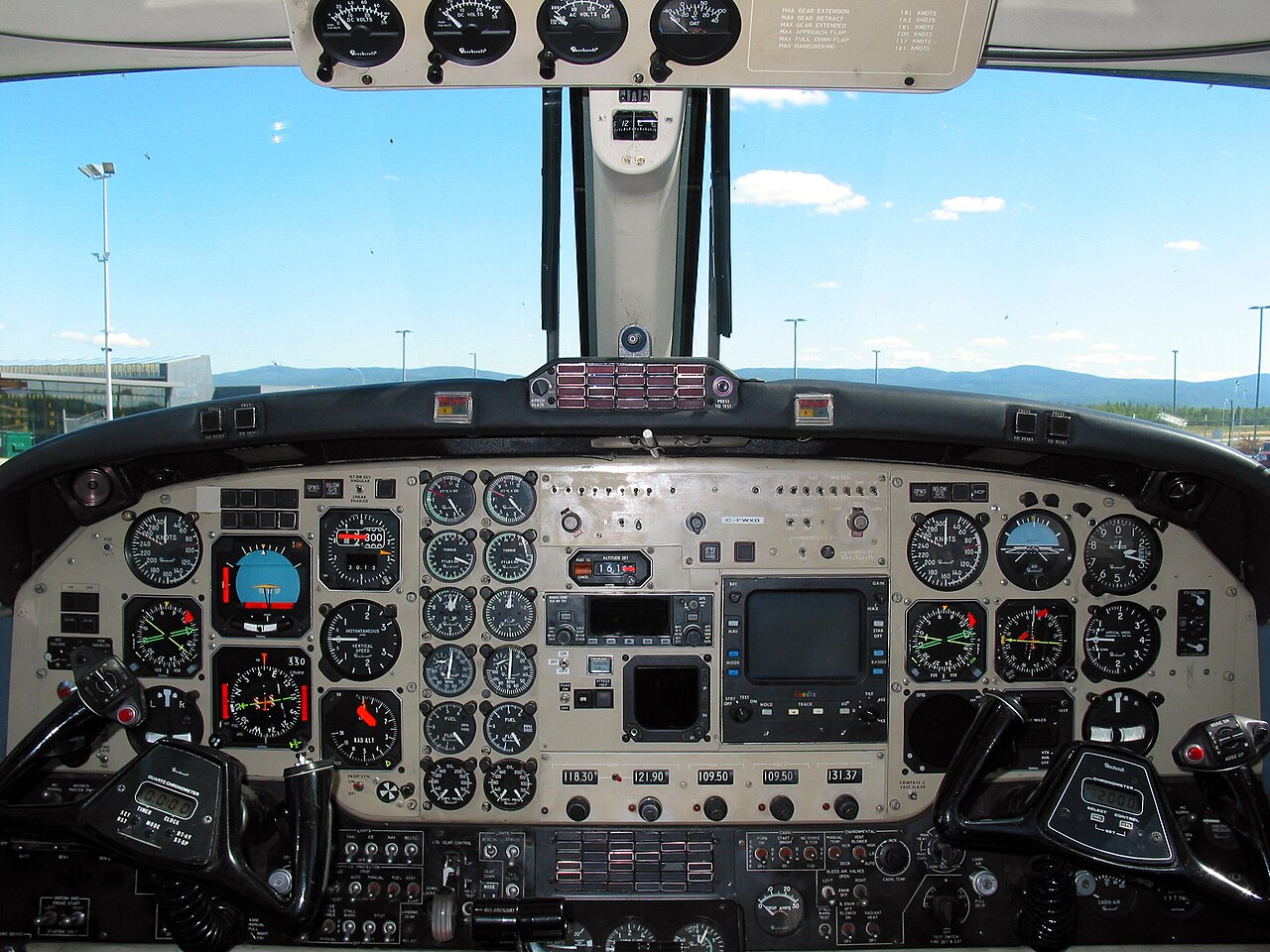
The environmental controls are below the copilot's main instrument panel. They command several different jobs: admitting engine bleed air, changing air temperature and moving cabin air. Cabin pressure is regulated separately by the pedestal controller and the valves in the aft pressure bulkhead. Start with the real panel location, then follow the named components in the drawings.
Find the highlighted area in the full cockpit, then inspect the enlarged controls below.
Enlarged environmental-control region below the copilot's instruments
“King Air 200 Panel (219959284).jpg” by Shawn, via Wikimedia Commons. CC BY-SA 2.0. Wikimedia 1280-pixel thumbnail; photograph unchanged. WWAOG adds a regional label and an enlarged viewport. The photograph and labeled photographic view are CC BY-SA 2.0. Original system drawings and assessment text are separate. No photographer or manufacturer endorsement is implied.
Find it in the photograph, then read its action, purpose and connection to the rest of the system. You can also choose a named item in the list. Keyboard users can use Tab and Enter or Space.
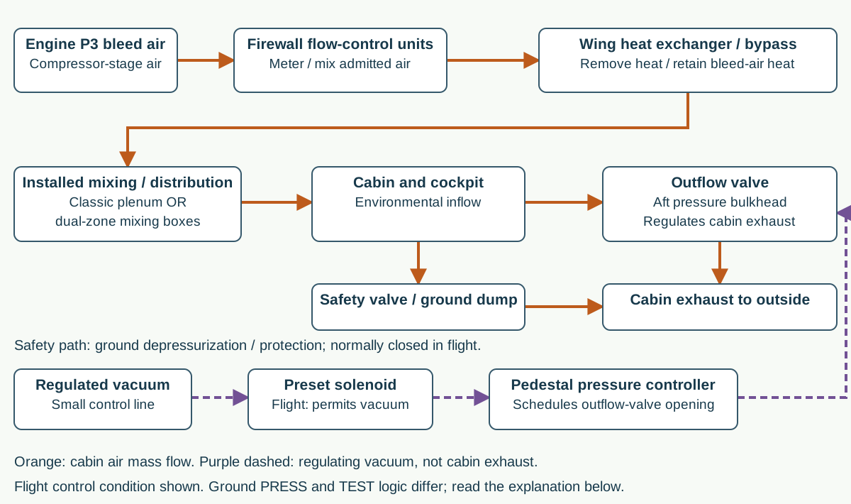
Environmental inflow, cabin exhaust and separate regulating vacuum
P3 bleed air passes through the firewall environmental flow-control units, wing heat exchangers or hot-air bypass, and the installed mixing/distribution system to the cabin. Cabin air exhausts through the aft outflow valve. Separate regulated-vacuum lines connect the controller and pressure-control solenoids; they do not carry cabin exhaust. The safety-valve path is for ground depressurization or protective relief; it is normally closed in flight. Select the diagram to inspect it full size.
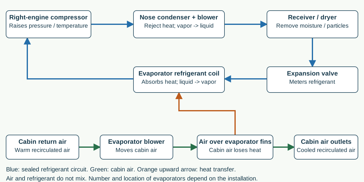
Refrigerant loop and separate cabin-air heat transfer
In a sealed loop the compressor supplies the condenser, receiver/dryer, expansion valve and evaporator before returning to the compressor. A separate cabin-air path goes through a blower and over the evaporator, where cabin heat transfers into the refrigerant. Select the diagram to inspect it full size.
Engine bleed air enters the cabin; the outflow valve regulates air leaving it
Original functional drawings, not an operating checklist or aircraft wiring schematic. Solid orange arrows show environmental air; purple dashed arrows show pressurization-control vacuum. The separate blue drawing carries refrigerant, not breathable air. Normal components and available supplies are assumed for these teaching examples.
1
P3 bleed air and the firewall flow-control units
P3 is compressed air taken from each engine compressor. A flow-control unit, abbreviated FCU in this environmental chapter, meters and mixes bleed air with outside air as applicable. The BLEED AIR VALVES control requests environmental airflow. It is not the engine fuel-control unit. Identify early pneumatic FCUs or later electronic FCUs from serial and kit records; classic cabin ducts do not automatically mean pneumatic FCUs.
2
Wing heat exchangers and hot-air bypass valves
A heat exchanger transfers heat out of the environmental air into separate outside cooling air. Routing more hot bleed air around the exchanger retains more heat for the cabin; routing it through the exchanger removes heat. The outside cooling air exits the wing. It is not the pressurization-control vacuum line or the cabin exhaust route.
3
Mixing plenum or dual-zone mixing boxes and cabin outlets
Classic ducts combine conditioned bleed air with recirculated or cooled cabin air at a mixing plenum. The dual-zone installation instead uses a venturi, mixing boxes and servo-operated valves to route warm air to cockpit and cabin outlets. A venturi uses the moving bleed-air stream to draw in cabin air. Electric blowers move recirculated air over evaporators. The classic and dual-zone layouts have different duct and blower controls.
4
Cabin pressure controller, outflow valve and safety valve
The pedestal controller uses regulated vacuum to control the outflow valve at the aft pressure bulkhead. Cabin air leaves through the valve opening, not through the controller or its small vacuum line. The safety valve provides protection and the ground depressurization route. Cabin pressure depends on both air entering and air leaving, including leakage.
5
Ground PRESS differs from TEST and flight
In the described ground PRESS condition, the energized preset solenoid blocks regulating vacuum to the controller and the energized safety solenoid supplies opening vacuum to the safety valve. In flight, those ground commands are removed and the controller regulates outflow. Ground TEST makes the control logic flight-like for the prescribed maintenance test. TEST is not a general instruction to pressurize a parked aircraft.
6
Compressor, condenser, receiver/dryer, expansion valve and evaporator
The right-engine-driven compressor raises refrigerant pressure and temperature. The nose condenser rejects heat to outside air and turns the refrigerant into liquid. The receiver/dryer removes moisture and particles; the expansion valve meters refrigerant into an evaporator. Evaporation absorbs heat from cabin air moving over the evaporator, and low-pressure refrigerant returns to the compressor. Cabin air stays outside the sealed refrigerant tubing.
Expected normal response: In the prepared normal heating example, admitted bleed air reaches the installed mixing/distribution system and selected outlets. A blower provides circulation; its operation alone does not prove refrigeration. During the stated in-flight pressure-control condition, the cabin pressure controller regulates the outflow valve while the cabin-altitude, differential-pressure and rate indications report different quantities. No photograph reading or universal pressure limit is used as acceptance.
Study reference: Study edition: Super King Air 200 Series MM 101-590010-19, supplied November 1, 2024 effective-page list; individual page dates and applicability retained. 21-00-00 pp.1-2; 21-01-00 pp.1-2; 21-10-00 p.1; 21-11-00 p.1; 21-21-00 pp.1-2; 21-30-00 p.1; 21-50-00 p.1; 21-51-00 pp.1-2; 21-60-00 pp.1-3. Current online revision status is not established by this study copy.
Use the diagram before diagnosing a fault
Control: Classic MANUAL TEMP: INCR versus DECR
Explanation: In the described classic manual-control arrangement, MANUAL HEAT or MANUAL COOL selects the manual mode. Holding MANUAL TEMP toward INCR commands more hot-air bypass and increased heating; DECR commands more cooling through the wing heat exchangers. Releasing the momentary switch stops the valve drive. The switch changes valve position, not a selected cabin-pressure altitude. Do not turn this functional explanation into a timed adjustment or all-model travel instruction.
Study reference: 21-60-00 pp.1-2. The classic manual-heat sequence and Pro Line 21/Keith simultaneous-valve branch are separate.
Control: Classic AUTO and VENT BLOWER
Explanation: In AUTO, the temperature control box compares the selected temperature with temperature-sensor feedback and commands heating/cooling. The classic VENT BLOWER has AUTO, LOW and HIGH positions. It moves air through the forward evaporator and cabin ducts. Temperature mode, blower speed and compressor operation are different observations. A blower can run while pressure or engine-speed protection prevents compressor operation.
Study reference: 21-00-00 p.2; 21-50-00 pp.1-2; 21-60-00 pp.1-3.
Control: Dual-zone CABIN and COCKPIT controls
Explanation: For the identified dual-zone branch, separate CABIN TEMP and COCKPIT TEMP knobs set the two zones in AUTO. The electronic environmental controller adjusts servo valves, blowers and compressor clutch operation. The ENVIR BLEED AIR switch selects NORMAL, AUTO or LOW flow; automatic response to heating/cooling demand requires environmental MODE in AUTO. Flow selection is separate from temperature selection. In MAN HEAT with blower controls at AUTO, the specified dual-zone blowers are OFF by design.
Study reference: 21-01-00 pp.1-2; 21-21-00 pp.1-2; 21-51-00 pp.1-2. Dual-zone applicability: BB-1978,BB-1988 and after;BL-152 and after;BY-1 and after.
Classic heating: name the commanded change
Think it through: Prepared classic manual-control record: bleed air is available, MANUAL HEAT is selected, and the technician holds MANUAL TEMP toward INCR. What change is being commanded, and what happens to the valve drive when the switch is released?
Explanation: More hot environmental air is routed around the wing heat exchanger for increased heating. Releasing the momentary switch stops its valve drive at the attained position. The blower speed and cabin-pressure set point have not been changed by that command. The installed task still governs valve sequence and any adjustment.
Dual-zone cooling: warm bleed air still has a job
Think it through: Prepared dual-zone cooling record: normal refrigerant cooling is available and the cabin evaporator blowers supply the cabin outlets. Where is most of the warm environmental bleed air routed when the cabin needs little or no heat, and why is this not a loss of pressurization supply?
Explanation: The mixing-box valves route most of that warm bleed air aft to the baggage/aft-cabin outlets. It still enters the pressure vessel. The linked cabin heat/bypass valves preserve an inflow route while cooled recirculated air serves the cabin outlets. Cooling the cabin and supplying pressurization are related but different jobs.
Ground PRESS: do not infer a failed compressor or pressure controller
Think it through: Prepared parked-aircraft record: the landing-gear ground logic is active and the cabin pressure switch is in PRESS. The cabin does not build pressure. Which normal ground control actions should be identified before treating this as a fault?
Explanation: The preset solenoid blocks controller vacuum and the safety solenoid supplies opening vacuum to the safety valve, allowing cabin air out. This is the described ground PRESS condition. A refrigerated-air compressor cools cabin air; it is not the compressor that supplies engine P3 bleed air. A maintenance pressure test has its own setup and precautions.
The photograph shows a conventional King Air 200 cockpit, not a verified dual-zone or Pro Line 21 installation. Its numbered label identifies the environmental-control region; individual placards are too small or obstructed for switch-by-switch photo labels. The drawings explain named controls from the supplied maintenance manual. Select the aircraft's distribution system and flow-control-unit type separately.
This guided photo activity explains the visible equipment. Selecting a label does not operate an aircraft control or record course completion. Continue with the system diagram and supplied fault record to practice troubleshooting.
Free course sample · KA200-021
Learn the relationship. Test your reasoning.
Try a short teaching exercise from the subject of King Air 200/B200 Air Conditioning, Heating and Pressurization. No account needed.
About 2 minutes
01 · Understand
Environmental bleed air enters the pressure vessel through the FCUs. Cabin air leaves through the outflow and safety valves. Vacuum connections control those valves; they do not carry the main cabin exhaust. In ground PRESS, the energized preset solenoid blocks vacuum to the cabin controller while the energized safety solenoid supplies vacuum that opens the safety valve.
Separate the inflow, vacuum-control and cabin-exhaust paths
Engine P3 / FCUs supply cabin inflow→
Ground PRESS opens the safety-valve dump path→
TEST/flight changes the controller vacuum configuration
02 · Read the supplied record
A fictional King Air 200-series ground-check record states: PRESS selected; weight-on-wheels confirmed; preset and safety solenoids energized; safety valve open; cabin differential near zero. The technician has not yet recorded the prescribed TEST response.
Original public teaching example based on the course’s published scope. Supplied records and values are training data. Aircraft maintenance uses current applicable instructions; this sample does not record course completion.
Our aircraft systems courses use manufacturer technical manuals to support pilots and maintenance personnel working in FAA- and EASA-regulated aviation. Training combines detailed system explanations, knowledge checks and interactive exercises for initial familiarization and recurrent study.
Training at your location
Your aircraft. Your team. A course built around both.
WWAOG offers tailored on-site courses for operators, maintenance organizations and government teams. We can shape the course around your aircraft configuration, installed systems, technician experience and operational training goals.
Tell us what your team needs
Aircraft model and equipment configuration
Location, group size and technician experience
System topics and desired learning outcomes
Preferred dates and available training resources
We’ll agree the scope, delivery plan and quotation before scheduling. Tailored on-site training is arranged separately from individual online course enrollment.
Read the applicable maintenance task, trace named circuits and identify complete parts rows. A 31-page illustrated handbook, nine lesson decisions, ten two-part practice cases and three document work orders connect aircraft effectivity, wiring sheets, connector views and IPC parts requests. Includes a separate 40-question final at 80%.