
King Air Pro Line 21 Attitude, Heading & Standby Diagnostics
Explore the named components, make a prediction, then connect the supplied result to the system. This workshop adds coached practice alongside the course handbook and assessed lab.
See the reference behind the screen
A heading indication combines sensing, stored aircraft corrections, selected source and presentation. Explore those relationships, then predict what each fictional record should show before revealing its result. These formative exercises supplement the course handbook and assessed lab.
Find the Pro Line 21 displays and standby instrument
Start with the real panel. Select a numbered area or its named button to learn what the display shows and which equipment supplies its information. These dark screens do not provide an attitude, heading or fault observation.
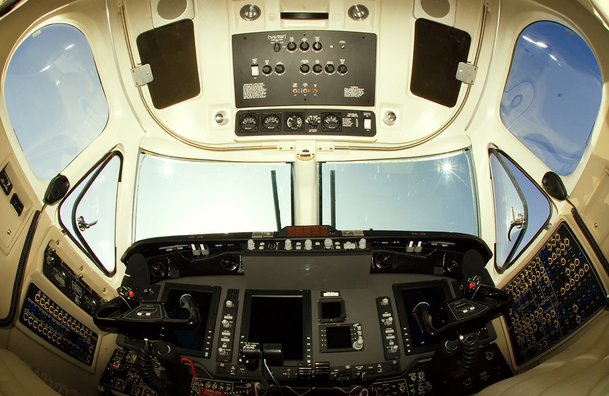
Beechcraft King Air 350. Cockpit (4104672117).jpg by Aleksandr Markin, CC BY-SA 2.0. Photograph unchanged; interactive labels by WWAOG. Photograph and labeled view: CC BY-SA 2.0; assessment text remains separate.
Scroll across the photograph to inspect the panel, or open the full-size cockpit photograph ↗. The named buttons below also select every teaching point.
Choose a numbered item
Find it in the photograph, then read its action, purpose and connection to the rest of the system. You can also choose a named item in the list. Keyboard users can use Tab and Enter or Space.
King Air 350 Pro Line 21 cockpit example. The course studies the supplied B300/B300C AHC-3000, FDU-3000 and ECU-3000 installation, with GH-3100 standby equipment, for the stated FL/FM effectivity. The photograph establishes visible locations; it does not identify every installed part or modification.
This guided photo activity explains the visible equipment. Selecting a label does not operate an aircraft control or record course completion. Continue with the system diagram and supplied fault record to practice troubleshooting.
Primary attitude/heading functional relationships. Separate arrows distinguish magnetic input, stored corrections and control commands; they are not a physical wiring diagram. Two AHC channels exist even where one functional block represents both.
Green outlines identify components named in the selected exercise record; they do not indicate a healthy component.
Named connections and what each arrow means
- FDU-3000 magnetic input → Two AHC-3000 computersInformation / signal: Magnetic measurements
- ECU-3000 stored corrections → Two AHC-3000 computersInformation / signal: Aircraft alignment / compass corrections
- MAG / DG and SLEW controls → Two AHC-3000 computersTask sequence: Heading mode and SLEW commands
- Two AHC-3000 computers → PFD / MFD indicationsInformation / signal: Computed reference information
- Source and screen-role controls → PFD / MFD indicationsTask sequence: Source selection and screen role: separate controls
FDU-3000 magnetic input
Measures components of the earth’s magnetic field for the AHC heading computation.
How it works with the rest
Each FDU uses a gimbaled two-axis magnetic sensor and a pendulous sensing element. The two FDUs are in the horizontal stabilizer. Their measurements contribute to heading; they do not supply the AHC’s inertial pitch and roll sensing. Magnetic installation conditions and compensation can therefore matter to a heading complaint even when attitude remains supported.
What the evidence must show
Separate a heading-reference observation from an attitude observation. A heading-only discrepancy narrows useful branches without identifying one failed part.
Selected: FDU-3000 magnetic input
Follow the change through the system.
Fictional initialized-channel record: magnetic slaved mode is selected. The FDU reference remains stable. A held SLEW command has moved the displayed heading away from that reference. Predict the response to releasing SLEW; no new fault or magnetic change is supplied.
Before the recorded change
Mode: magnetic slaved. SLEW: held. FDU reference: stable. Displayed heading: temporarily displaced from the FDU reference.
Next observation
Choose your prediction before revealing the supplied result.
Reference: Textron 130-590031-11, B300/B300C Maintenance Manual, 34-21-00 p. 1, April 1, 2018; 34-21-07 Table 502 I, p. 508, April 15, 2023. Supplied Chapter 34 PDF pp. 71 and 89.
Course applicability and study references
Primary AHC-3000, FDU-3000 and ECU-3000 attitude/heading functions in the supplied B300/B300C Pro Line 21 tasks, effectivity FL-381, FL-383 and After; FM-12 and After. Match the installed equipment and current applicable instructions for aircraft work. The displayed challenges are supplied learning records, not instructions to manipulate an aircraft.
- Primary sensing and heading modes
Textron 130-590031-11, Super King Air B300/B300C Maintenance Manual, 34-21-00 p. 1 and 34-21-05 p. 401, April 1, 2018; supplied Chapter 34 PDF pp. 71 and 79. Defines the separate AHC, FDU and ECU roles, FDU location, magnetic/DG modes and SLEW-release behavior.
- AHC 1 comparator evidence
34-21-07 Table 502 G, pp. 506–507, April 15, 2023; supplied PDF pp. 87–88. The exercise uses only the explicitly named AHC 1 pitch challenge and return, with its initialization and NORM setup.
- Source selection and display roles
34-21-07 Table 502 E, p. 505, and Table 502 I–J, p. 508, April 15, 2023; supplied PDF pp. 86 and 89. These defined functional-test snapshots support the control relationships shown here.
Original learning diagrams and supplied training records explain the stated relationships. Current aircraft-effective instructions and authorization govern actual maintenance.