
King Air B300/B300C Fuel Systems & Troubleshooting
Explore the named components, make a prediction, then connect the supplied result to the system. This workshop adds coached practice alongside the course handbook and assessed lab.
King Air fuel paths: collection, transfer, crossfeed and indication
Trace how the standard B300/B300C collects fuel in each nacelle, uses motive fuel to transfer AUX contents and connects a source to the opposite engine. Open each component to follow its purpose and interactions. In four fictional comparisons, predict the change before revealing the supplied record, then interpret a separate system relationship.
Find the fuel quantity indicators, then follow the fuel paths
Start at the real fuel panel beside the pilot. The two round instruments indicate fuel quantity. Then use the diagrams to separate three questions: Where is the fuel stored? How does it reach the engine? What fuel does each gauge measure?
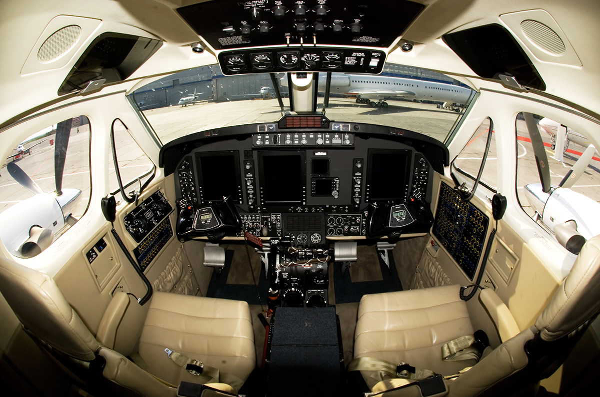
Fuel panel beside the pilot - enlarged orientation view
Hawker Beechcraft 350 King Air (B300). N60125.Cockpit (3928566846).jpg by Aleksandr Markin, CC BY-SA 2.0. Photograph unchanged; WWAOG interactive label and enlarged viewport. Photograph and labeled photographic view: CC BY-SA 2.0. Original teaching diagrams and course assessment text are separate.
Scroll across the photograph to inspect the panel, or open the full-size cockpit photograph ↗. The named buttons below also select every teaching point.
Choose a numbered item
Find it in the photograph, then read its action, purpose and connection to the rest of the system. You can also choose a named item in the list. Keyboard users can use Tab and Enter or Space.
Follow fuel from the wing and auxiliary tanks to the engine
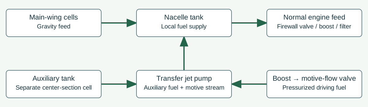
Keep quantity measurement separate from fuel movement
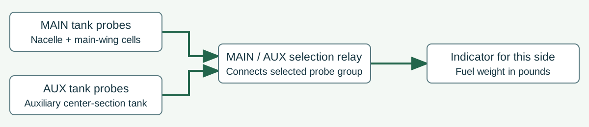
Follow normal fuel delivery and auxiliary transfer
Follow one side first; the other side has the same main/auxiliary arrangement. Arrows show functional fuel paths, not physical tube positions. The engine's metering and nozzle system continues beyond this airframe overview.
Main-wing fuel drains to the nacelle tank
Interconnected main-wing cells and the integral wet-wing tank feed the nacelle by gravity. The nacelle is the local fuel collection and engine-supply tank. Vent and relief paths allow fuel to move without collapsing or pressurizing the cells improperly.
Boost pressure supports the engine supply
Normal supply leaves the nacelle through the firewall shutoff valve, engine-driven boost pump and firewall fuel filter toward the engine fuel system. The electric standby pump in the nacelle is a separate boost source; the two boost pumps are not a compulsory series pair.
Pressurized motive fuel drives the transfer jet pump
A boost source supplies pressurized fuel through the motive-flow valve to the jet pump. This driving stream is called motive fuel. It creates the pumping action that draws auxiliary fuel into the transfer stream; there is no electric motor inside the jet pump.
Auxiliary fuel transfers into the nacelle
The jet pump draws from the auxiliary tank and delivers to the nacelle. AUTO uses the automatic fuel-transfer module to control the motive-flow valve. AUX TRANSFER OVERRIDE bypasses that module's command path; it does not create boost pressure or repair a blocked transfer path.
Keep crossfeed separate from tank replenishment
The crossfeed valve connects the supply sides so fuel from one side can supply the opposite engine. The supplying side requires standby-boost support. Crossfeed does not transfer fuel from one storage cell to the opposite storage cell; auxiliary-to-nacelle transfer is a different path.
Expected normal response: With MAIN selected, each indicator reads its side's nacelle plus main-wing fuel group. With AUX momentarily selected, each reads its auxiliary tank. Changing that selector changes the displayed quantity group, not the amount of fuel physically in a tank. A low nacelle level and a larger combined MAIN quantity can therefore require investigation of gravity replenishment rather than immediate gauge replacement.
Study reference: Textron 130-590031-11, 28-00-00 pp.1-6; 28-40-00 pp.1-2. Supplied B300/B300C study edition.
King Air 350 (B300), N60125, photographed in 2009. This guide teaches the standard main/auxiliary B300/B300C fuel arrangement in the supplied manual. ER/CER additions are separate. The photo locates the panel; its small switch legends and gauge readings are not clear enough for a reading or switch-operation exercise.
This guided photo activity explains the visible equipment. Selecting a label does not operate an aircraft control or record course completion. Continue with the system diagram and supplied fault record to practice troubleshooting.
Fuel routes, pressure inputs and electrical indications have different boundaries
Recorded state: before the supplied change
Green outlines identify components named in the selected exercise record; they do not indicate a healthy component.
Named connections and what each arrow means
- Main wing storage and gravity feed → Nacelle collecting tankPhysical relationship: Gravity replenishment through the flapper
- Vent, relief and overflow paths → Main wing storage and gravity feedPhysical relationship: Wing pressure communication
- Vent, relief and overflow paths → Nacelle collecting tankPhysical relationship: Distinct nacelle pressure/overflow relationships
- Nacelle collecting tank → Normal and standby boost sourcesPhysical relationship: Local fuel available to pressure sources
- Normal and standby boost sources → Engine-supply isolation and pressure boundaryPhysical relationship: Pressure support for the engine-supply boundary
- Normal and standby boost sources → Motive valve and auxiliary jet pumpPhysical relationship: Pressurized motive-fuel source
- Center-section AUX tank → Motive valve and auxiliary jet pumpPhysical relationship: AUX fuel drawn into the jet pump
- Motive valve and auxiliary jet pump → Nacelle collecting tankPhysical relationship: Combined motive and entrained-fuel delivery
- Nacelle collecting tank → Center-section AUX tankPhysical relationship: Separate excess-transfer overflow return
- Center-section AUX tank → AUTO logic, float and NO TRANSFERInformation / signal: Fuel-present float input
- Motive valve and auxiliary jet pump → AUTO logic, float and NO TRANSFERInformation / signal: Motive-pressure switch input
- AUTO logic, float and NO TRANSFER → Motive valve and auxiliary jet pumpElectrical power: Electrical motive-valve command
- Normal and standby boost sources → Opposite-engine crossfeed connectionPhysical relationship: Supplying-side standby pressure support
- Opposite-engine crossfeed connection → Engine-supply isolation and pressure boundaryPhysical relationship: Opposite-engine route; receiving firewall required
- Opposite-engine crossfeed connection → Normal and standby boost sourcesInformation / signal: Source standby-pump command
- Opposite-engine crossfeed connection → AUTO logic, float and NO TRANSFERInformation / signal: Receiving-side automatic transfer inhibition
- Main wing storage and gravity feed → MAIN/AUX capacitance indicationInformation / signal: Main-wing probe contribution
- Nacelle collecting tank → MAIN/AUX capacitance indicationInformation / signal: MAIN nacelle probe and reference contribution
- Center-section AUX tank → MAIN/AUX capacitance indicationInformation / signal: AUX selected probe contribution
- Nacelle collecting tank → Separate nacelle low-level warningInformation / signal: Local level at the separate optical sensor
Main wing storage and gravity feed
Stores the wing portion of MAIN fuel and replenishes the nacelle through the gravity-feed path.
Supplied record: Wing fuel present; gravity feed open.
How it works with the rest
On each side, the standard main group includes the nacelle, two leading-edge cells, two box-section cells and an integral wet-wing tank. Wing fuel flows toward the nacelle by gravity. A flapper at the nacelle end limits reverse flow into the wing. The two MAIN groups together hold 380 usable US gallons; this is not 380 gallons on each side.
What the evidence must show
Distinguish fuel remaining in the wing from fuel reaching the local nacelle. A combined MAIN indication does not locate that fuel.
Selected: Main wing storage and gravity feed
Follow the change through the system.
Fictional standard left-side record: wing fuel and local nacelle fuel are present, the gravity path and vents are initially open, and normal boost is available. The change is a confirmed obstruction of the main-wing gravity path. The first question concerns the instant that obstruction occurs. The revealed record separately supplies a later low nacelle level; no depletion time or quantity is calculated. AUX transfer is unavailable in this comparison, so it cannot replenish the nacelle.
Before the recorded change
Initial record: gravity feed available; nacelle contains fuel; local-level sensor covered. AUX transfer is not available for this comparison.
Next observation
Choose your prediction before revealing the supplied result.
Reference: Textron 130-590031-11: 28-00-00 pp. 1-3 and Figure 1 sheets 1-2; 28-40-00 pp. 1-2. Standard installation.
Course applicability and study references
Standard B300/B300C airframe fuel and capacitance quantity installation in Textron 130-590031-11, with the PT6A-60A engine-supply interface. 350ER/CER additional tanks, sequence controls and quantity installations are separate. Arrows summarize functional routes and control influences, not an installation drawing. These qualitative records supply no flow rate, depletion time, operating sequence, maintenance acceptance or aircraft release.
- Standard B300/B300C storage, boost, AUX transfer and crossfeed
Textron 130-590031-11 ATA 28: 28-00-00 pp. 1-6,101-102; 28-20-00 pp. 1-3. Supplied chapter LEP November 1, 2025; cited description pages April 1, 2018. Figure 1 sheets 1-2 show the storage and physical routes. Standard 380 + 159 = 539 usable US gal installation; ER/CER architecture is compared separately in 28-21-00 pp. 1-3.
- Capacitance quantity, group selection and separate local warning
Textron 130-590031-11: 28-40-00 pp. 1-2 (April 1, 2018), and p. 103 step 25/note (November 1, 2025). MAIN/AUX selection, probe/reference functions, local electro-optical warning and an AUX fault affecting MAIN are distinct relationships.
- PT6A-60A fuel-system interface
P&WC 3034342 PT6A-60A/-60AG/-61 Maintenance Manual, supplied Revision 43 October 7, 2013: 73-00-00 pp. 1,5-6 (individual pages November 5, 1999). The represented B300 interface is PT6A-60A. Pump pressurizing, FCU metering and configured dump/purge functions are downstream of the airframe supply boundary; no supplier operating sequence or numerical setting is transferred to this workshop.
Original learning diagrams and supplied training records explain the stated relationships. Current aircraft-effective instructions and authorization govern actual maintenance.