
King Air B300/B300C Electrical Troubleshooting
Explore the named components, make a prediction, then connect the supplied result to the system. This workshop adds coached practice alongside the course handbook and assessed lab.
King Air B300/B300C: locate the first missing transition
Trace energy, control and protection as separate paths. Use the applicable distribution arrangement to interpret a generator, ground-power or converter record. This optional practice preserves the existing course lab and assessment requirements.
Read the overhead electrical instruments, then follow the power
Find the two generator loadmeters, the combined voltmeter/battery ammeter and the bus selector in the real cockpit. A loadmeter tells you how much a generator is supplying; the selected voltmeter reading tells you the voltage at one selected bus. Those are different observations.
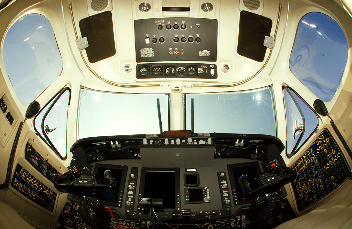
Enlarged overhead electrical instruments
Beechcraft King Air 350. Cockpit (4104672117).jpg by Aleksandr Markin, CC BY-SA 2.0. Photograph unchanged; WWAOG labels and enlarged viewport. Photograph and labeled photographic view: CC BY-SA 2.0. Original functional diagrams and course assessments are separate.
Scroll across the photograph to inspect the panel, or open the full-size cockpit photograph ↗. The named buttons below also select every teaching point.
Choose a numbered item
Find it in the photograph, then read its action, purpose and connection to the rest of the system. You can also choose a named item in the list. Keyboard users can use Tab and Enter or Space.
Follow power through the named buses
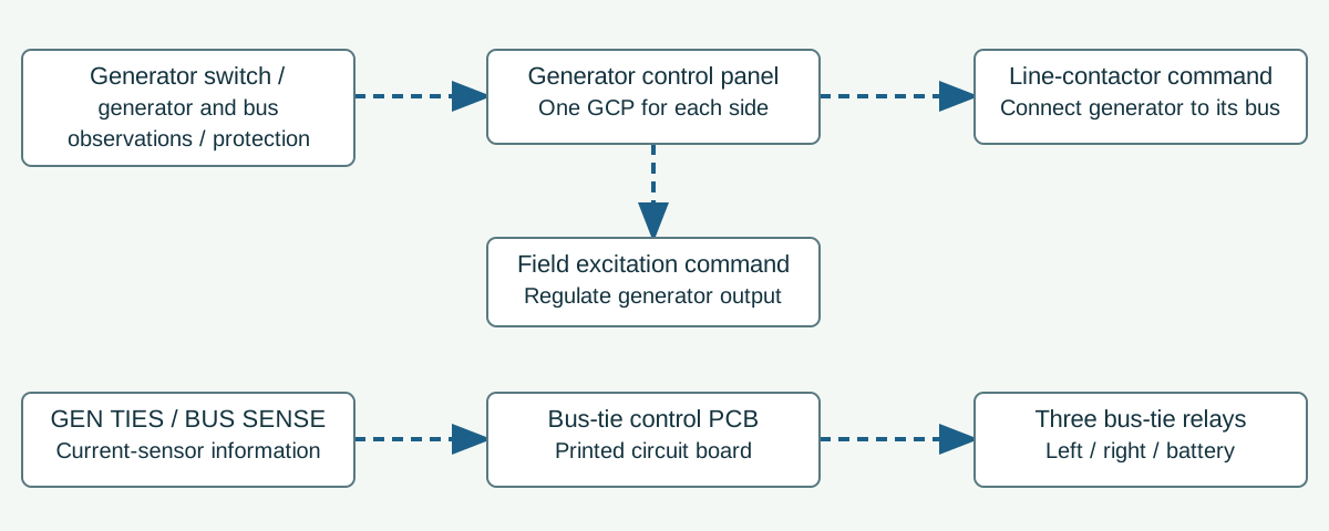
Separate GCP and bus-tie commands from generator output current
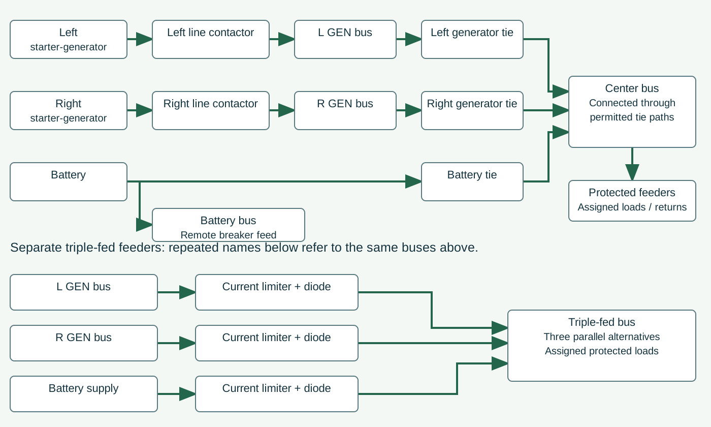
Three power sources, controlled bus ties and separate triple-fed paths
Original functional overview of the supplied B300/B300C DC arrangement. Solid green arrows represent power distribution. Dashed blue arrows on the separate command diagram represent control actions, not generator output current. Individual load feeds and returns must still be identified on the applicable wiring diagram.
Battery, battery bus and battery tie
The battery provides stored energy. Its remote control circuit breaker feeds the battery bus; the battery tie is a separate switching path to the center bus. The battery bus is not in series with the battery tie. Hot-battery branches are separate unswitched connections. BAT OFF does not establish that every battery-connected circuit is isolated.
Starter-generator and generator control panel
Each starter-generator supplies mechanical starting torque or generates DC electricity. Each has its own generator control panel, abbreviated GCP in this course. The GCP controls field excitation to regulate voltage; generator output does not pass through the GCP as the main load-current route.
Line contactor and generator bus
The GCP separately commands the line contactor when the necessary generator, bus, switch and protection conditions are satisfied. Closing the contactor connects that starter-generator to its generator bus. A generator can build voltage yet remain disconnected from the bus.
Generator ties, current sensors and center bus
The left and right generator bus ties connect their generator buses to the center bus. The bus-tie control printed circuit board uses switch and current-sensor information to control the ties and isolate an affected bus. The three ties are left generator, right generator and battery; a tie is a switching device, not another power source.
Triple-fed bus: three parallel protected feeds
The left generator bus, right generator bus and battery supply can feed the triple-fed bus through separate current-limiter and diode paths. These are parallel alternatives. One remaining feed can keep the bus alive; that does not prove all three feeders are intact.
Protected load feeds and return
Equipment receives power through its assigned protected feeder and switching path and needs a complete return to the supplying source. A live bus is different from a powered individual load. Use the voltmeter selection and load indications as observations, then test the named path required by the applicable task.
Expected normal response: Read this prepared later-system battery-only record: no external power, generators not operating, BAT BUS NORM, BAT ON and generator ties open. BAT and CTR indicate battery-derived voltage; TPL FED indicates slightly less; generator and EXT PWR positions indicate zero, and both generator loadmeters indicate zero percent. The energized TPL FED position does not establish energized generator buses. This is an explanation of the supplied check record, not a stand-alone aircraft operating sequence.
Study reference: Textron 130-590031-11, 24-00-00 p.1; 24-30-00 pp.1-4; 24-60-00 pp.1,601-602. Instrument identities: 31-10-00 Figure 9 p.11. Supplied study edition; exact aircraft effectivity remains separate.
Use the diagram before diagnosing a fault
Voltage selection is not bus-tie control
Think it through: The technician rotates the overhead VOLTMETER BUS SELECT switch from CTR to TPL FED without changing any power switches. Has this action closed a generator tie?
Explanation: No. It selected a different point for the voltmeter to observe. Generator ties are controlled through GEN TIES, BUS SENSE, current-sensor and bus-tie control-board logic.
A live triple-fed bus does not prove three good feeds
Think it through: One triple-fed current-limiter path is open while another protected feeder still supplies the bus. Must the triple-fed bus indicate zero volts?
Explanation: No. The remaining parallel feeder can keep it energized. The live reading does not clear the open feeder or prove that every connected load has power.
King Air 350 Pro Line 21 cockpit example. The photograph shows instrument locations, not a verified electrical test or the aircraft's full installed configuration. The normal bus example below uses the later B300/B300C distribution group: FL-381, FL-383 and after; FM-12 and after. Earlier distribution and battery chemistry are separate checks in the course.
This guided photo activity explains the visible equipment. Selecting a label does not operate an aircraft control or record course completion. Continue with the system diagram and supplied fault record to practice troubleshooting.
Functional electrical boundaries: power arrows show working-energy relationships; control and return details are explained in the component cards. This is not an aircraft wiring diagram.
Green outlines identify components named in the selected exercise record; they do not indicate a healthy component.
Named connections and what each arrow means
- Starter-generators and battery → Center bus and bus tiesElectrical power: Line-contactor power to center-bus ties
- Generator control panels → Starter-generators and batteryInformation / signal: Field and line-contactor command
- External power → Center bus and bus tiesElectrical power: External relay to center bus
- Starter-generators and battery → Triple-fed distributionElectrical power: Protected source feeds; battery path separate
- Center bus and bus ties → Assigned loads, converter and returnElectrical power: Other assigned bus supplies
- Triple-fed distribution → Assigned loads, converter and returnElectrical power: Selected protected load supplies
Starter-generators and battery
The left and right engine-driven starter-generators supply DC energy to their respective generator buses through line contactors. The identified battery supplies a separate stored-energy source; its chemistry and switched/hot connections must be established independently.
How it works with the rest
Residual voltage, field establishment, regulated output and connection to the bus are successive boundaries. A later success cannot be assumed from an earlier one.
What the evidence must show
Output at the machine does not by itself prove that its line contactor was commanded or delivered power.
Selected: Starter-generators and battery
Follow the change through the system.
Fictional qualitative generator record: the selected installation is identified; machine output is established, but the control panel has not issued the line-contactor close command. No relay-contact test is provided.
Before the recorded change
Machine output is established; the line-contactor close command is absent. Predict delivery from that machine.
Next observation
Choose your prediction before revealing the supplied result.
Reference: 130-590031-11 ATA 24, 24-30-00 pp.1–3; fictional missing-command record.
Course applicability and study references
B300/B300C study from supplied Beechcraft 130-590031-11 ATA 24; effective-page list November 1, 2025, with individual task dates. Distribution, battery chemistry, avionics, AC architecture and modifications require their own identification. Functional diagram only. All experiment records are fictional; they create no maintenance limit or release decision.
- Beechcraft 130-590031-11, supplied ATA 24
Effective-page list November 1, 2025; individual task dates vary. 24-00-00 p.1, electrical architecture; 24-30-00 pp.1–4, field/regulation, line-contactor command, D/E/M equalization and four closed-device prerequisites; 24-40-00 pp.1,201, external connection sensing and the battery-voltage precaution before external power is applied; 24-50-00 pp.1–2 and 24-60-00 p.1, bus-tie control, distribution and energized-OFF/open avionics relay logic.
- Installed RR-18 branch and original WWAOG records
24-31-00 p.1 and 24-31-01 p.501: match installed converter and actual paired PFD/AHC 1 and MFD/AHC 2 loads. Fictional measurements and missing observations do not establish serviceability. Existing lab, independent review, final and completion requirements remain unchanged.
Original learning diagrams and supplied training records explain the stated relationships. Current aircraft-effective instructions and authorization govern actual maintenance.