
Caravan PT6A-114/-114A Fuel System & Troubleshooting
Explore the named components, make a prediction, then connect the supplied result to the system. This workshop adds coached practice alongside the course handbook and assessed lab.
Earlier Caravan fuel: replenishment, boost and trustworthy indications
Follow fuel from the vented wings into the underfloor reservoir, through the motive-powered ejector or electric auxiliary boost pump and the earlier-engine firewall filter. Open each component to connect its purpose with the evidence it needs. Four paired exercises then separate stored fuel from pump inlet supply, ON operation from NORM command, delivery bypass from contamination recovery, and a complete resistance chain from an individual sensor.
Recognize the fuel annunciations before tracing the fuel path
Three visible annunciations concern different conditions: auxiliary-pump operation, fuel-manifold pressure and fuel-selector warning logic. Select each label to learn what it tells you. Then follow the PT6A-114/-114A fuel route, including the separate paths for motive fuel and instrument signals.
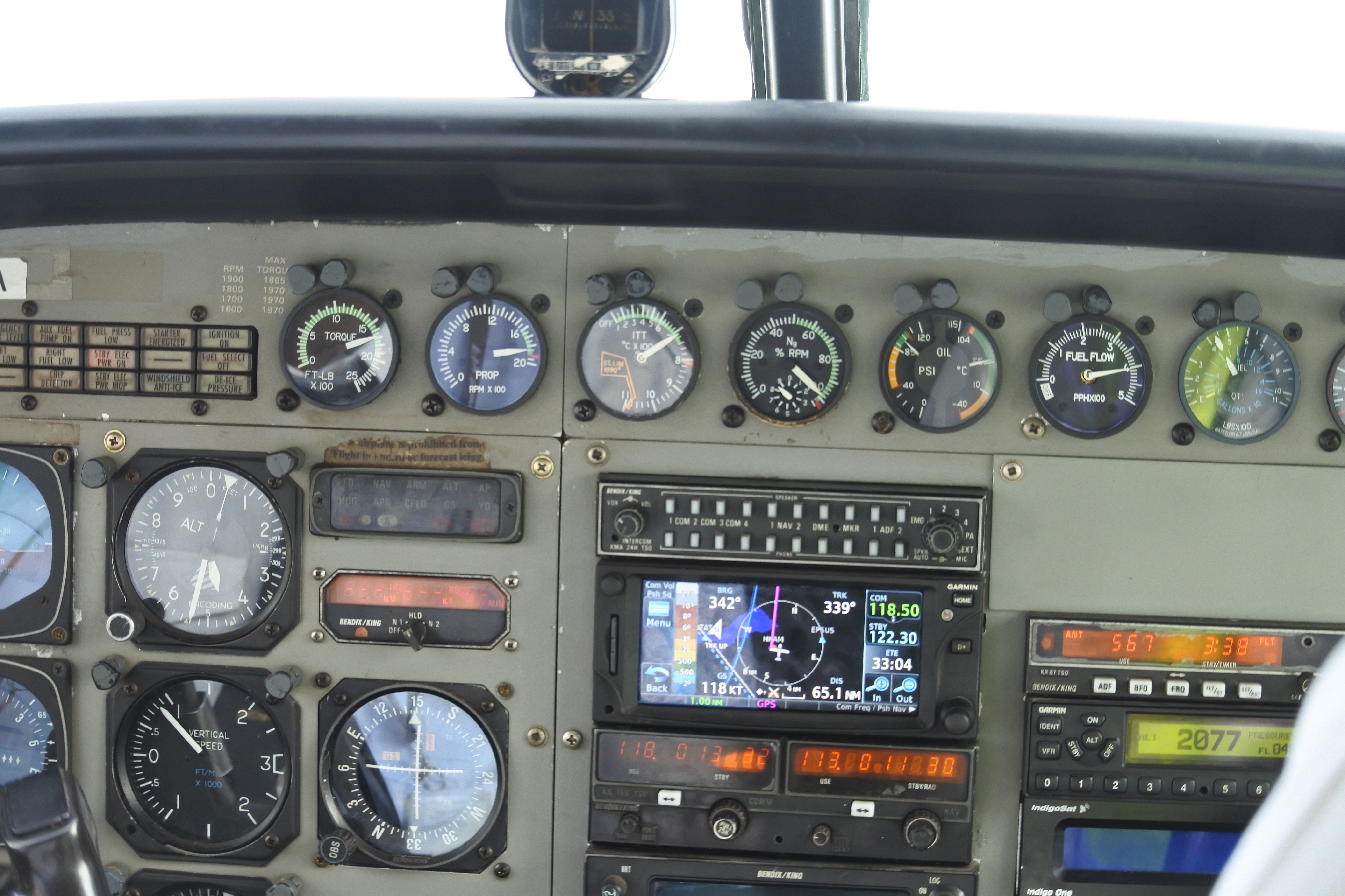
Enlarged fuel-annunciator area
Photo: "Cessna Caravan Cockpit.jpg" by flightlog, via Wikimedia Commons and Flickr, CC BY 2.0. Photograph unchanged; enlarged viewport and teaching labels by WWAOG. The photograph and labeled view are available under CC BY 2.0. Assessment text remains separate. No photographer or manufacturer endorsement is implied.
Scroll across the photograph to inspect the panel, or open the full-size cockpit photograph ↗. The named buttons below also select every teaching point.
Choose a numbered item
Find it in the photograph, then read its action, purpose and connection to the rest of the system. You can also choose a named item in the list. Keyboard users can use Tab and Enter or Space.
PT6A-114/-114A: from wing storage to engine nozzles
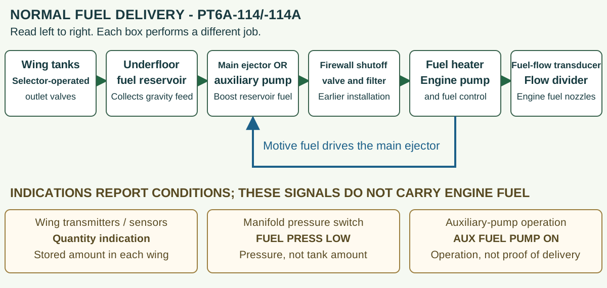
PT6A-114/-114A: from wing storage to engine nozzles
Original functional teaching diagram for the earlier Caravan fuel arrangement. Green arrows show supply to the engine. The blue return arrow shows motive fuel that drives the ejector. Amber cards describe indications; they are separate from fuel delivery. This is not a wiring diagram or operating checklist.
Wing tanks and overhead selectors
Fuel is stored in two integral wing tanks. Each overhead selector mechanically operates the two outlet shutoff valves in its wing. With the selected paths open, gravity carries fuel into the underfloor reservoir. These selectors are valves, not wing transfer-pump switches.
Reservoir and boost pumps
The reservoir is the low collection point supplying the submerged main ejector and auxiliary electric pump. Motive fuel is the stream whose energy drives the ejector jet. That jet draws in (entrains) reservoir fuel. The motive branch comes from the engine pump/control system; the auxiliary pump uses electrical power. Both need fuel at their inlet.
Firewall shutoff valve and firewall filter
Boosted fuel passes through the manifold, firewall shutoff valve and earlier-installation firewall filter. Closing the shutoff valve interrupts engine delivery even if an upstream pump is operating. The filter removes contamination; a bypass indication is a separate filter finding.
Fuel heater, engine-driven pump and fuel control
The heater conditions fuel before the engine-driven pump/control assembly. The engine-driven pump supplies pressure for the engine system; the fuel control meters the amount delivered to the engine. This is different from the airframe boost pumps moving fuel out of the reservoir.
Fuel-flow transducer, flow divider and nozzles
Metered fuel passes the fuel-flow transducer and reaches the flow divider and engine fuel nozzles. The transducer sends a flow signal to the instrument. The flow indicator reports a rate; wing quantity instruments report stored amount.
Venting, quantity and shutdown fuel are separate branches
Tank venting and the reservoir-to-tank vent paths support gravity feed. Quantity transmitters or later CAN sensors send information to the installed indicators; they do not carry the engine fuel supply. Fuel left at shutdown drains to the earlier installation's collection can. That can is separate from the underfloor reservoir.
Expected normal response: With fuel available, the selected tank paths open and venting unobstructed, the reservoir replenishes and supplies the boost pumps. During the prescribed running condition, engine motive flow supports the main ejector; auxiliary-pump operation depends on the selected command and actual pressure condition. A fuel-quantity indication, a pump-operation light and measured manifold pressure answer different questions. Follow the applicable test before judging an indication or changing a component.
Study reference: Cessna Model 208 MM D2078, supplied Revision 42, 28-01-00 pp.1, 3-5 (Jan. 1, 2024); 28-40-00 p.1 (Dec. 1, 2015). Figure 1 Sheet 2; 28-10-00 p.1; 28-45-00 p.102 (Apr. 1, 2019).
Use the diagram before diagnosing a fault
G1000-equipped Caravan: find tank quantity in pounds
This section covers G1000-equipped aircraft separately from the analog photo guide. Use the installed aircraft and software guide. The NXi comparison below is specifically from Garmin 190-02138-01 Rev. C, System Software 2499.08 or later.
- At the lower edge of the MFD, select ENGINE (Engine on NXi), then SYSTEM (System on NXi). This opens the Engine System Display.
- Under FUEL, read QTY L LBS and QTY R LBS for indicated left- and right-wing tank quantities in pounds. FFLOW PPH is a rate in pounds per hour.
- Read FUEL TOTALIZER separately: LB REM starts from the pilot-entered amount and changes with fuel flow; LB USED accumulates fuel used from flow since its reset. These calculations do not use the tank-quantity indicators.
- In the classic guide, ENGINE or BACK returns to the default Engine Display. Match the installed softkey level and guide.
| Display label | Example | What it tells you |
|---|---|---|
| QTY L LBS | 600 | Indicated fuel in the left wing tank. |
| QTY R LBS | 500 | Indicated fuel in the right wing tank. |
| FFLOW PPH | 420 | Fuel flow rate: pounds per hour, not pounds stored. |
| LB REM | 1200 | Pilot-initialized remaining-fuel calculation, updated from fuel flow. |
| LB USED | 300 | Fuel used calculated from flow since reset. |
Which increment applies? For the NXi configuration identified above, the displayed QTY L/R values change in 25-lb increments with the PT6A-114A and 10-lb increments with the PT6A-140. These are display increments, not sensor-accuracy limits. Do not apply either value to every earlier G1000 version or to the PT6A-114 without its applicable guide.
The NXi LB REM adjustment menu also has +10 LB and -10 LB keys. Those keys change the entered totalizer amount; they do not change measured tank fuel or establish the QTY display increment.
Worked example: Original training numbers: QTY L 600 plus QTY R 500 gives 1100 lb indicated across the two tanks. LB REM 1200 could result from a 1500-lb totalizer entry minus 300 lb used. The 100-lb difference is a discrepancy to reconcile using the applicable instructions and verified fuel/record information; do not simply force one value to match the other.
Original WWAOG teaching diagram and fictional values; not an OEM screenshot, aircraft check result or fuel-verification procedure.
Study reference: Garmin classic G1000 Caravan Pilot's Guide 190-00749-00 Rev. B pp.88-91; Garmin G1000 NXi Caravan Pilot's Guide 190-02138-01 Rev. C pp.94-97, Figure 3-3 (System Software 2499.08 or later).
This real earlier Caravan has separate analog engine instruments and a discrete annunciator panel. It is not a Grand Caravan EX or a verified G1000 installation. Later PT6A-114/-114A aircraft may instead show fuel messages on a Garmin PFD and quantity on the MFD. Match the aircraft serial number, installed equipment and applicable manual. A photograph does not establish a serviceable aircraft or an active warning.
This guided photo activity explains the visible equipment. Selecting a label does not operate an aircraft control or record course completion. Continue with the system diagram and supplied fault record to practice troubleshooting.
Trace gravity feed, motive-powered boost, electric backup and shutdown collection as different routes.
Recorded state: before the supplied change
Green outlines identify components named in the selected exercise record; they do not indicate a healthy component.
Named connections and what each arrow means
- Vented wing storage → Selectors and linked outlet valvesPhysical relationship: Stored fuel reaches the paired selected outlets
- Selectors and linked outlet valves → Underfloor reservoirPhysical relationship: Gravity feed replenishes the local reservoir
- Underfloor reservoir → Wing and reservoir ventsPhysical relationship: Reservoir vent communicates with the wing-tank vent section
- Vented wing storage → Wing and reservoir ventsPhysical relationship: Wing tanks communicate with their outside vent routes
- Underfloor reservoir → Motive-powered ejectorPhysical relationship: Local fuel is available to the ejector inlet
- Underfloor reservoir → Electric auxiliary boostPhysical relationship: The same local fuel is available to the auxiliary inlet
- Heater, engine pump and FCU → Motive-powered ejectorPhysical relationship: FCU motive fuel supplies ejector energy
- Motive-powered ejector → Boost manifold and pressure sensingPhysical relationship: Ejector-boosted reservoir fuel
- Electric auxiliary boost → Boost manifold and pressure sensingPhysical relationship: Electrically boosted reservoir fuel
- Boost manifold and pressure sensing → Electric auxiliary boostInformation / signal: Low-pressure-related automatic command in NORM
- Boost manifold and pressure sensing → Firewall fuel shutoffPhysical relationship: Common boosted delivery toward the firewall
- Firewall fuel shutoff → Earlier-engine firewall filterPhysical relationship: Earlier-engine supply through the open firewall barrier
- Earlier-engine firewall filter → Heater, engine pump and FCUPhysical relationship: Filtered or bypassed fuel to heater and engine pump
- Heater, engine pump and FCU → Flow report, divider and simplex nozzlesPhysical relationship: Metered fuel through the flow transducer to the divider
- Flow report, divider and simplex nozzles → Shutdown dump and EPA collection canPhysical relationship: Residual manifold fuel through the shutdown dump route
- Vented wing storage → Installed quantity-sensing branchInformation / signal: Float/sensor response reports stored wing quantity
Vented wing storage
Store fuel above the underfloor reservoir so selected fuel can replenish it by gravity.
Supplied record: Verified stored fuel.
How it works with the rest
Each integral wing tank supplies two mechanically linked outlet shutoff valves. Stored quantity, an available outlet and a continuing supply into the reservoir are different observations. A wing can contain fuel while its selected feed or vent path prevents that fuel from replenishing the reservoir.
What the evidence must show
Separate the measured wing quantity from actual outlet travel, feed continuity and reservoir-level change.
Selected: Vented wing storage
Follow the change through the system.
Fictional PT6A-114A Caravan fuel-path trainer. Verified fuel remains in both wings and the reservoir initially contains fuel. The represented boost source and downstream route stay functional. Reveal closes the gravity-feed path into the reservoir while demand continues; it does not empty the reservoir immediately. No flight duration or aircraft operating action is assigned.
Before the recorded change
Wing feed is open. Reservoir level and represented manifold pressure are steady while fuel is drawn toward the engine.
Next observation
Choose your prediction before revealing the supplied result.
Reference: Cessna D2078 Rev 42:28-01-00 p 1 and Figure 1 sheet 2/p3;28-10-03 p 201.
Course applicability and study references
Formative visual supplement for the PT6A-114/-114A Caravan using the supplied Cessna Model 208 Maintenance Manual D2078 Revision 42 compilation, June 1, 2024. Engine plumbing and quantity-generation effectivity are independent. The earlier-engine path is not the PT6A-140 MFSOV, delay-relay or ecology installation. Original fictional records teach relationships; task-specific setup remains attached to the one numerical resistance exercise. This workshop does not supply aircraft operating instructions, complete maintenance procedures or a release to service.
- Cessna Model 208 Maintenance Manual D2078 Revision 42
Supplied compilation June 1, 2024.28-01-00 pp 1,3–5 (January 1, 2024),Figure 1 sheet 2: earlier-engine wing/reservoir, independent motive path, auxiliary selection, firewall filter and EPA-can relationships.28-01-00 p 101 distinguishes the PT6A-140 boost troubleshooting branch.
- Fuel ventilation, reservoir and selector interfaces
28-10-03 p 201 (June 3, 2002),28-22-00 p 201 (May 1, 2024),28-23-00 p 201 (December 1, 2012): reservoir/wing/outside vent sections, co-located boost sources and mechanically linked wing selectors.
- Earlier series quantity and contaminant recovery
28-40-00 p 1 (December 1, 2015),28-41-00 pp 201,204–206 (January 1, 2024): independent sensing effectivity, digital-meter caution, installed full-wing 224–242-ohm band and connection/ground-first separation.28-00-02 pp 201–204 (March 1, 2017): contaminant-specific recovery and recurrence-source relationships.
- PT6A-114/-114A engine delivery interface
73-10-00 p 1 (July 1, 2016) and28-01-00 Figure 1 sheet 2: heater, engine pump/filter, FCU, flow transducer, ten primary/four secondary simplex nozzles and shutdown dump to EPA can. Detailed internal engine limits are not inferred from the airframe description.
Original learning diagrams and supplied training records explain the stated relationships. Current aircraft-effective instructions and authorization govern actual maintenance.