
Grand Caravan EX Fuel System & Troubleshooting
Explore the named components, make a prediction, then connect the supplied result to the system. This workshop adds coached practice alongside the course handbook and assessed lab.
Grand Caravan EX fuel paths and diagnostic boundaries
Follow wing fuel through the selector valves and underfloor reservoir to the motive-powered ejector, electric auxiliary boost pump and PT6A-140 supply. The ecology tank handles shutdown-fuel recovery, while the fuel-level sensors provide separate quantity data. Use four supplied maintenance records to predict, reveal and explain these relationships.
Find the MFD, then trace the Grand Caravan EX fuel system
Locate the center multifunction display (MFD) and the physical keys along its lower edge. Their functions follow the labels shown on the current display page. Then learn the EX fuel route and how to distinguish indicated wing quantity from the fuel totalizer.
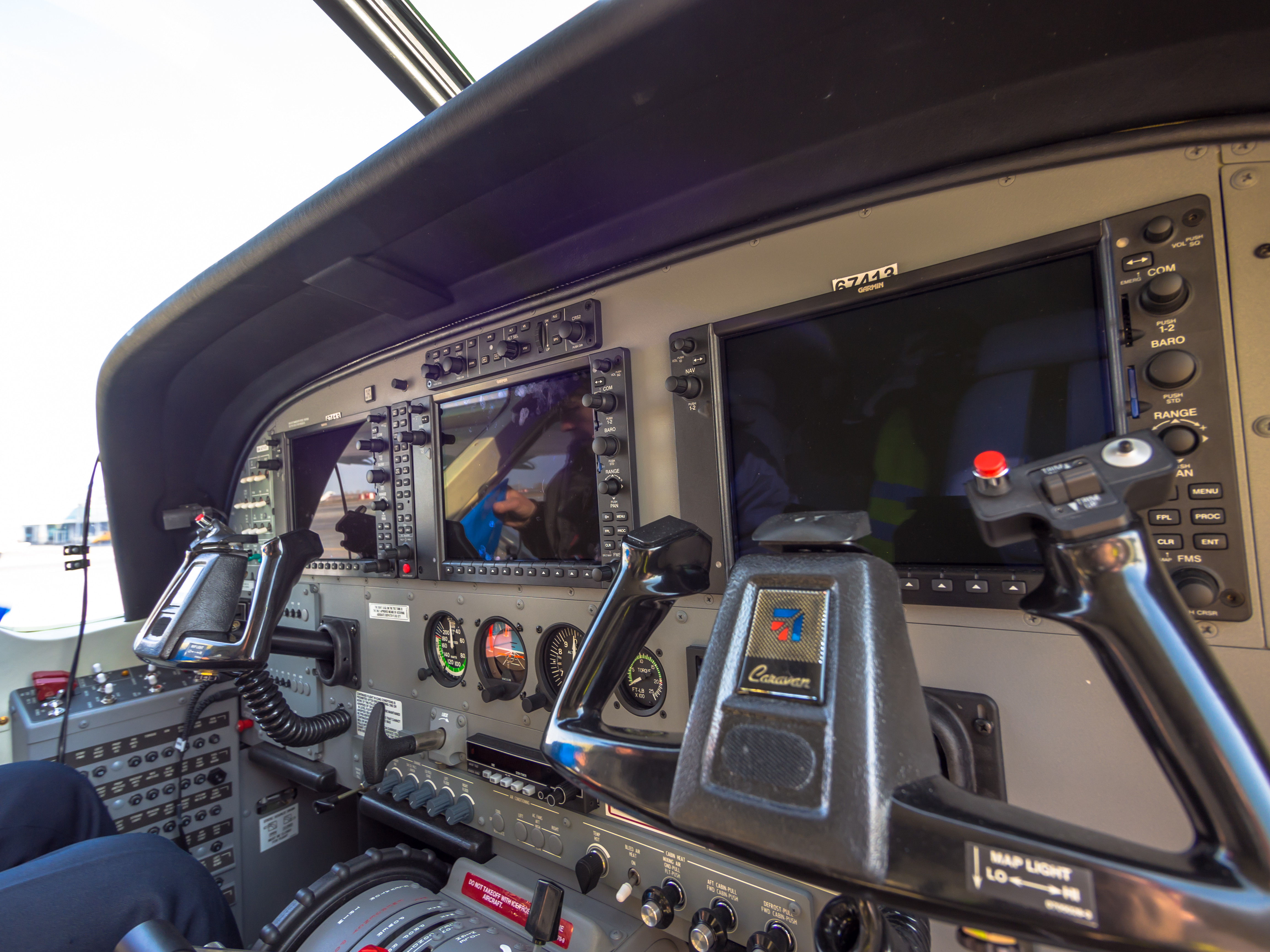
Enlarged center MFD and physical lower softkey row
Photo: "Cessna Grand Caravan cockpit (8649554760).jpg" by Alex Polezhaev, via Wikimedia Commons and Flickr, CC BY 2.0. Photograph unchanged; enlarged viewport and teaching labels by WWAOG. The photograph and labeled view are available under CC BY 2.0. Assessment text remains separate. No photographer or manufacturer endorsement is implied.
Scroll across the photograph to inspect the panel, or open the full-size cockpit photograph ↗. The named buttons below also select every teaching point.
Choose a numbered item
Find it in the photograph, then read its action, purpose and connection to the rest of the system. You can also choose a named item in the list. Keyboard users can use Tab and Enter or Space.
Grand Caravan EX: follow fuel delivery, motive flow and ecology recovery
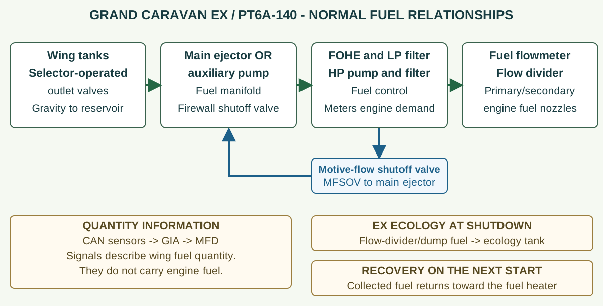
Grand Caravan EX: follow fuel delivery, motive flow and ecology recovery
Original functional teaching diagram for the PT6A-140 EX arrangement. Green arrows show the main delivery route. The blue branch supplies motive fuel through its shutoff valve to the main ejector. Separate cards distinguish quantity information and shutdown-fuel recovery; these are different functions. This is not a wiring diagram or maintenance procedure.
Wing tanks, outlet valves and reservoir
Each overhead tank selector mechanically operates the two outlet shutoff valves in its wing. Open selected paths let gravity carry fuel to the underfloor reservoir. Wing vents and reservoir-to-tank vent paths support replenishment. Stored wing fuel and fuel actually reaching the reservoir are distinct observations.
Main ejector, auxiliary pump and MFSOV
The submerged main ejector and auxiliary electric pump draw from the reservoir. Motive fuel from the engine fuel-control system drives the ejector jet, which draws in reservoir fuel. The electric pump provides another boost method. In the identified EX installation, NORM arms automatic auxiliary support and opens the motive-flow shutoff valve (MFSOV). Both pumps still need a supplied inlet.
Manifold, firewall valve and FOHE/LP filtration
Boosted fuel reaches the manifold and firewall shutoff valve, then the engine fuel-oil heat exchanger (FOHE) assembly and low-pressure (LP) filtration. The FOHE transfers heat between engine oil and fuel. This EX arrangement is different from the earlier Caravan's separate firewall filter and heater.
High-pressure pump, HP filter and fuel control
The engine high-pressure (HP) pump raises fuel pressure for the engine system. Fuel passes the HP filter and fuel control. The fuel control meters engine demand; it is not the airframe ejector or auxiliary boost pump. A fuel-control branch also supports the separate motive-fuel path back to the reservoir ejector.
Flowmeter, flow divider and fuel nozzles
Metered fuel passes the flowmeter, then the flow divider distributes it to the primary and secondary engine fuel-nozzle circuits. The flow indication reports a rate in pounds per hour. It is not the amount stored in either wing tank.
Ecology tank and next-start recovery
At shutdown, fuel from the flow-divider/dump-valve path enters the EX ecology (drain) tank. The recovery arrangement draws that fuel back toward the fuel heater on the next start. This is a separate collection/recovery function, not the underfloor reservoir feeding the boost pumps and not the earlier manually drained collection can.
Expected normal response: With selected tank feed and venting available, the reservoir replenishes and supplies the boost pumps. Established engine motive flow supports the main ejector; auxiliary operation depends on the selected command and actual pressure condition. Wing quantity, reservoir level, manifold pressure and pump-operation messages describe different parts of the system. Compare them in the prescribed test condition before assigning a failed component.
Study reference: Cessna Model 208 MM D2078, supplied Revision 42, 28-01-00 pp.1-5, Figure 1 Sheet 1; 28-10-00 p.1. Garmin G1000 Caravan Pilot's Guide 190-00749-00 Rev. B pp.19,88-91. 28-40-00 p.1; 28-45-00 p.102.
Use the diagram before diagnosing a fault
G1000-equipped Caravan: find tank quantity in pounds
This lesson addresses Garmin-equipped Grand Caravan EX aircraft. The display increment described here is from Garmin G1000 NXi Caravan guide 190-02138-01 Rev. C, System Software 2499.08 or later, with the PT6A-140. The real photograph is used only to locate the MFD and its physical softkey row; it does not verify an EX or NXi installation.
- At the lower edge of the MFD, select ENGINE (Engine on NXi), then SYSTEM (System on NXi). This opens the Engine System Display.
- Under FUEL, read QTY L LBS and QTY R LBS for indicated left- and right-wing tank quantities in pounds. FFLOW PPH is a rate in pounds per hour.
- Read FUEL TOTALIZER separately: LB REM starts from the pilot-entered amount and changes with fuel flow; LB USED accumulates fuel used from flow since its reset. These calculations do not use the tank-quantity indicators.
- In the classic guide, ENGINE or BACK returns to the default Engine Display. Match the installed softkey level and guide.
| Display label | Example | What it tells you |
|---|---|---|
| QTY L LBS | 600 | Indicated fuel in the left wing tank. |
| QTY R LBS | 500 | Indicated fuel in the right wing tank. |
| FFLOW PPH | 420 | Fuel flow rate: pounds per hour, not pounds stored. |
| LB REM | 1200 | Pilot-initialized remaining-fuel calculation, updated from fuel flow. |
| LB USED | 300 | Fuel used calculated from flow since reset. |
Which increment applies? For the PT6A-140 NXi configuration identified above, the displayed left- and right-wing quantity values change in 10-lb increments. This is a display increment, not a sensor-accuracy limit. Match the installed software and aircraft guide; do not assume every earlier Garmin installation uses the same increment.
The NXi LB REM adjustment menu also has +10 LB and -10 LB keys. Those keys change the entered totalizer amount; they do not change measured tank fuel or establish the QTY display increment.
Worked example: Original training numbers: QTY L 600 plus QTY R 500 gives 1100 lb indicated across the two tanks. LB REM 1200 could result from a 1500-lb totalizer entry minus 300 lb used. The 100-lb difference is a discrepancy to reconcile using the applicable instructions and verified fuel/record information; do not simply force one value to match the other.
Original WWAOG teaching diagram and fictional values; not an OEM screenshot, aircraft check result or fuel-verification procedure.
Study reference: Garmin classic G1000 Caravan Pilot's Guide 190-00749-00 Rev. B pp.88-91; Garmin G1000 NXi Caravan Pilot's Guide 190-02138-01 Rev. C pp.94-97, Figure 3-3 (System Software 2499.08 or later).
This is a real classic G1000 Caravan cockpit used for display-location orientation. It is not a verified Grand Caravan EX or NXi photograph. The screens are dark, so no fuel value or softkey function is being read from the photograph. The separate teaching display below uses manual-identified EX/NXi labels and clearly fictional numbers.
This guided photo activity explains the visible equipment. Selecting a label does not operate an aircraft control or record course completion. Continue with the system diagram and supplied fault record to practice troubleshooting.
Trace wing replenishment to the reservoir, then separate motive/electric boost, engine delivery, ecology recovery and CAN quantity information.
Recorded state: before the supplied change
Green outlines identify components named in the selected exercise record; they do not indicate a healthy component.
Named connections and what each arrow means
- Wing storage and selector valves → Underfloor fuel reservoirPhysical relationship: Selected gravity-feed outlets
- Wing and reservoir vent paths → Wing storage and selector valvesPhysical relationship: Tank pressure equalization supports feed
- Wing and reservoir vent paths → Underfloor fuel reservoirPhysical relationship: Reservoir vents to both wings
- Underfloor fuel reservoir → MFSOV and reservoir ejectorPhysical relationship: Fuel entrained at ejector inlet
- Underfloor fuel reservoir → Electric auxiliary boost pumpPhysical relationship: Fuel at electric pump inlet
- PT6A-140 engine fuel interfaces → MFSOV and reservoir ejectorPhysical relationship: Engine motive stream through MFSOV
- MFSOV and reservoir ejector → Manifold pressure and firewall boundaryPhysical relationship: Normal ejector boosted supply
- Electric auxiliary boost pump → Manifold pressure and firewall boundaryPhysical relationship: Alternative electric boosted supply
- Manifold pressure and firewall boundary → PT6A-140 engine fuel interfacesPhysical relationship: Supply past the firewall shutoff
- PT6A-140 engine fuel interfaces → Ecology tank, float and non-return valvePhysical relationship: Residual flow-divider/dump fuel at shutdown
- Ecology tank, float and non-return valve → PT6A-140 engine fuel interfacesPhysical relationship: Recovered fuel returns toward heater
- Wing storage and selector valves → CAN sensors, GIA and quantity calibrationInformation / signal: Physical tank level is the sensed input
Wing storage and selector valves
Store wing fuel and open or close each wing’s two gravity-feed outlets.
Supplied record: Wing fuel confirmed; one linked valve short of required travel.
How it works with the rest
Each overhead selector mechanically moves two shutoff valves in its own wing through cables and an interconnect. The selected wing supplies the underfloor reservoir by gravity. Selector position is a command; actual travel of both valves and continuity of the affected feed path are separate observations.
What the evidence must show
Keep independently confirmed wing fuel, both valve endpoints and continuing reservoir replenishment in the same record.
Selected: Wing storage and selector valves
Follow the change through the system.
Fictional Grand Caravan EX/PT6A-140 maintenance record. Wing fuel is independently confirmed. One selected wing valve stops short of its required travel, and a separate prescribed inspection records a restricted wing vent. The reservoir level falls. An auxiliary pressure comparison meets while its inlet remains submerged. The follow-up corrects only the selector linkage; the vent restriction remains. These are supplied paper records, not work instructions.
Before the recorded change
The selected wing has both a valve-travel defect and a vent restriction. Local auxiliary pressure meets only during the supplied-inlet comparison.
Next observation
Choose your prediction before revealing the supplied result.
Reference: Cessna D2078 Revision 42: 28-01-00 p. 1 and Figure 1 sheet 1, p. 2 (Jan 1, 2024); 28-23-00 p. 201 (Dec 1, 2012).
Course applicability and study references
Optional formative companion to TM-030 Rev E for the supplied Cessna D2078 Revision 42 PT6A-140 branch, 208B2197 and 208B5000-and-on. The pressure case separately identifies its NXi serial/software/switch branch. These fictional paper records explain relationships; they do not supply engine-run sequences, calibration procedures or maintenance release. Existing core lab, final and certificate requirements remain separate.
- Cessna Model 208 Maintenance Manual D2078 Revision 42
Supplied compilation dated June 1, 2024. Chapter 28 LEP and 28-01-00 pp. 1–5 (Jan 1, 2024), including both actual Figure 1 sheets, distinguish EX and earlier installations. 28-10-00 p. 1 (Mar 1, 2020) explains ecology float/recovery/non-return roles.
- Identified pressure-reporting branch
28-00-00 pp. 101–102 (May 1, 2024), CMC event 1112: 208B2197 or 208B5809-and-on incorporating G1000 NXi software v.2499.23-and-on; SN011, below 2.5 psi during start/RUN. Kept separate from the general 4.75 psi description. No universal switch-calibration limit is asserted.
- CAN quantity and known-fuel comparison
28-40-00 p. 1 (Dec 1, 2015); 28-45-00 pp. 102–107 (Apr 1, 2019), including Table 105; pp. 501–506 (Jan 1, 2018). Green activity, individual identity, exact electrical configuration and physical calibration remain separate. The last record explicitly supplies the complete setup and task-specific range.
- PT6A-140 engine interface
D2078 Chapter 73 LEP (May 1, 2024); 73-10-00 p. 1 (Jul 1, 2016), physical PDF 3708, confirms FOHE, pump/control, duplex distribution and EX ecology recovery. Linked engine tasks remain necessary for detailed component work. The original map does not reproduce OEM artwork.
Original learning diagrams and supplied training records explain the stated relationships. Current aircraft-effective instructions and authorization govern actual maintenance.