
Grand Caravan EX Electrical Power & Troubleshooting
Explore the named components, make a prediction, then connect the supplied result to the system. This workshop adds coached practice alongside the course handbook and assessed lab.
Grand Caravan EX starter-generator, standby alternator and buses
Explore how the main starter-generator, optional standby alternator, contactors, bus feeders and conversion equipment supply electrical loads. Predict a response, reveal the observations and identify what each measurement establishes. This optional practice preserves the existing course lab and assessment requirements.
Find the electrical panels, then follow power to the equipment
Start at the left side of the pilot seat. The upper switch panel controls electrical functions; the rows of circuit breakers below protect individual circuits. Learn those locations in the real photo, then follow the named battery, generator and avionics paths in the diagram.
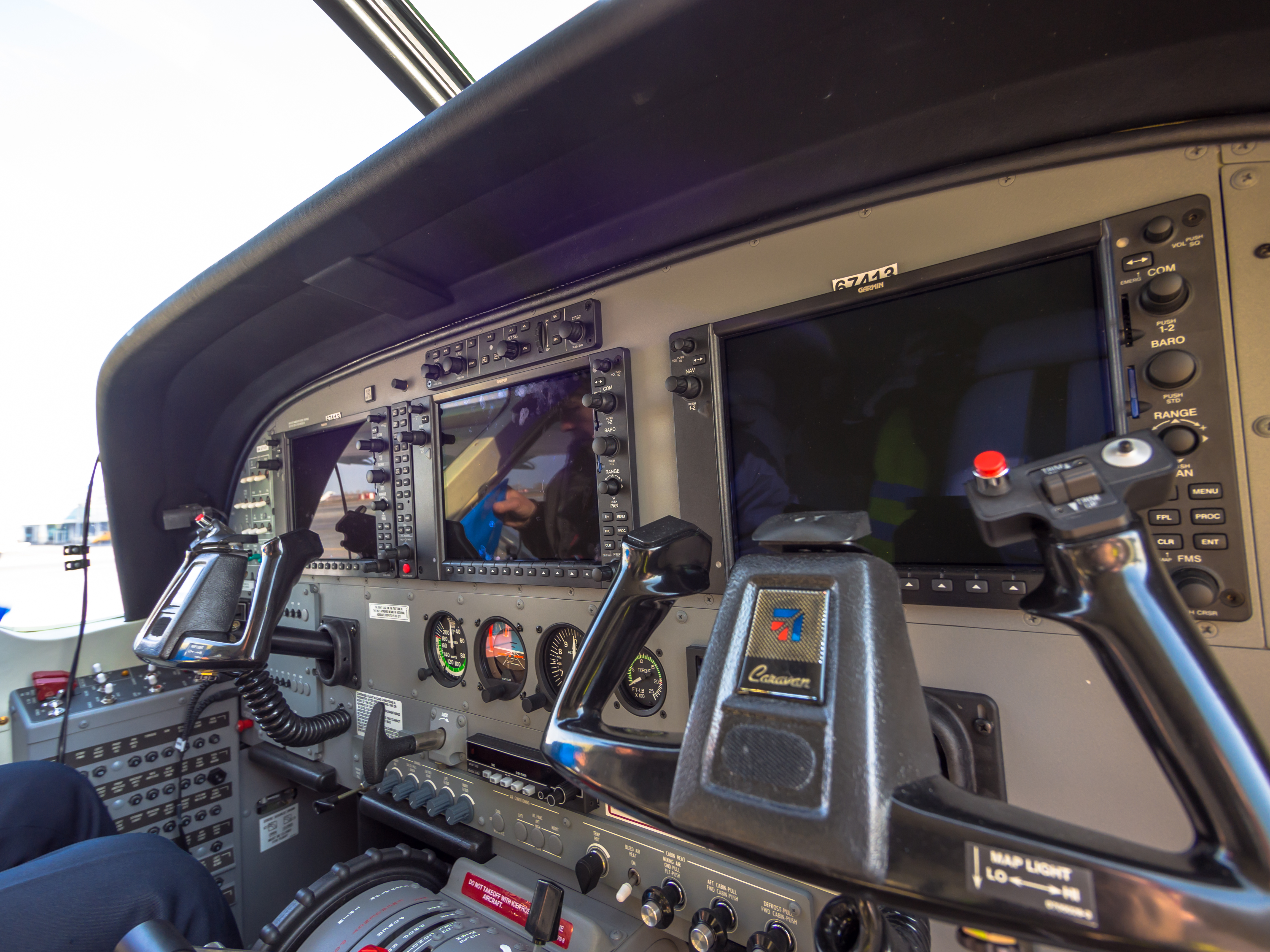
Enlarged left-side electrical panel regions
“Cessna Grand Caravan cockpit (8649554760).jpg” by Alex Polezhaev, via Wikimedia Commons and Flickr. CC BY 2.0. Photograph unchanged; WWAOG region labels and enlarged viewport. The photograph and labeled photo view are available under CC BY 2.0. Assessment text remains separate. No photographer or manufacturer endorsement is implied.
Scroll across the photograph to inspect the panel, or open the full-size cockpit photograph ↗. The named buttons below also select every teaching point.
Choose a numbered item
Find it in the photograph, then read its action, purpose and connection to the rest of the system. You can also choose a named item in the list. Keyboard users can use Tab and Enter or Space.
A normal electrical path has supply, switching, protection, equipment and return
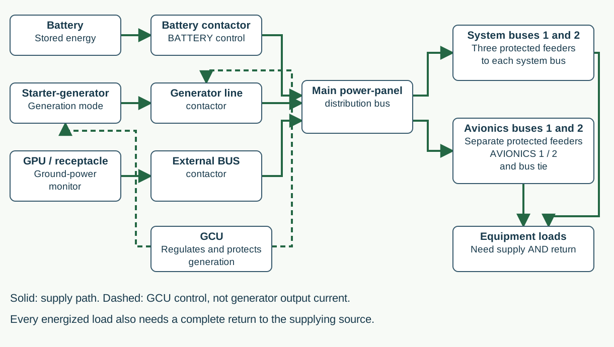
A normal electrical path has supply, switching, protection, equipment and return
Original functional teaching diagram of the described Caravan electrical arrangement. Solid arrows trace electrical supply; dashed arrows show generator control unit (GCU) control. Branch boxes summarize distribution, not individual wires or terminal numbers.
BATTERY switch and battery contactor
The battery stores electrical energy. With the battery path connected, the battery contactor connects it to the power distribution bus. The BATTERY switch controls this connection; it does not prove the battery has enough usable capacity. Battery OFF does not remove power from the separate battery bus.
Starter-generator, GCU and generator line contactor
The engine-driven starter-generator acts as a motor during starting and a generator during generation. The generator control unit (GCU) regulates and protects generation. With GENERATOR ON, the GCU controls the line contactor that connects generator output to the main power bus. The GCU control path is separate from the high-current output path.
External power receptacle, monitor and contactors
A ground power unit (GPU) supplies power through the receptacle. The ground-power monitor checks the incoming supply. EXTERNAL POWER BUS selects the aircraft-bus path; STARTER selects the separate starting path. A connected GPU is not proof that either contactor is closed.
Main power-panel bus and system-bus feeders
A bus bar is a conductor that distributes power to several circuits. The described No. 1 and No. 2 system buses each have three parallel feeder wires, with source-end current limiters and receiving-end pull-type breakers. One open feeder does not necessarily make the whole bus go dark.
AVIONICS 1, AVIONICS 2 and the avionics bus tie
Each avionics bus has its own feeder and switch/circuit breaker. AVIONICS 1 controls bus 1; AVIONICS 2 controls bus 2. The guarded AVIONICS BUS TIE connects the two buses when selected under the applicable procedure. This is different from the three-feeder system-bus arrangement.
Equipment load, return path and electrical indications
Equipment consumes power only when it has an available supply and a complete return path. In the described G1000 display example, BUS VOLTS reports bus voltage, GEN AMPS reports generator current, and BAT AMPS reports battery charge or discharge. They answer different questions; voltage alone does not measure battery capacity.
Expected normal response: In a prepared normal-generation record, the generator line contactor is closed, the power distribution bus is energized, and selected loads draw current through their protected feeders and return paths. Positive BAT AMPS indicates battery charging in the described display; negative BAT AMPS indicates discharge. A powered bus does not by itself prove that every parallel feeder is intact.
Study reference: Cessna Model 208 MM D2078 Revision 42 compilation: 24-30-00 p.1; 24-31-00 p.201; 24-50-00 p.201. EX POH/AFM 208BPHCUS-01 Rev. 1 (May 22, 2013), section 7 pp.7-89–7-98: historical configuration example for switch functions and display meanings, not NXi effectivity or present operating limits.
Use the diagram before diagnosing a fault
AVIONICS 1 OFF does not mean the generator failed
Think it through: Training record: the main bus is powered, AVIONICS 1 is OFF, AVIONICS 2 is ON, the tie is OFF, and no alternate feed is connected. Which avionics bus should receive its normal feeder supply?
Explanation: No. 2 avionics bus. Its own switch/breaker is ON. No. 1 is switched OFF in this stated setup. First account for these control positions before treating the unpowered No. 1 bus as a generator fault.
A voltage reading and charging current describe different things
Think it through: Training record: BUS VOLTS is stable and BAT AMPS is negative. What does the battery-current sign tell you?
Explanation: The battery is discharging in this display convention. Stable voltage does not prove battery charging or battery capacity. Keep the bus-voltage observation and battery-current observation separate when you follow the applicable task.
One open feeder can hide behind a powered bus
Think it through: Training record: one of the three No. 1 system-bus feeder current limiters is open, and the other two paths are intact. Must the whole No. 1 system bus be unpowered?
Explanation: No. The two remaining parallel paths can still feed that bus. Seeing bus voltage does not clear the open limiter or establish the full permitted feeder capability. This is why the diagram shows both the common bus and its protected feeder paths.
This is a classic G1000 Caravan cockpit location example. The two numbered labels identify panel regions, not individual switches: their placards are too blurred or obscured to read reliably. The course’s worked EX/NXi electrical cases use their separately identified installation.
This guided photo activity explains the visible equipment. Selecting a label does not operate an aircraft control or record course completion. Continue with the system diagram and supplied fault record to practice troubleshooting.
Functional electrical boundaries: power arrows show working-energy relationships; control and return details are explained in the component cards. This is not an aircraft wiring diagram.
Green outlines identify components named in the selected exercise record; they do not indicate a healthy component.
Named connections and what each arrow means
- Main starter-generator and GCU → System-bus feeders, limiters and contactorsElectrical power: Power delivery
- Optional standby alternator and ACU → System-bus feeders, limiters and contactorsElectrical power: Conditional support
- Battery and external-power paths → System-bus feeders, limiters and contactorsElectrical power: Selected power path
- System-bus feeders, limiters and contactors → Inverter, controller and outletsElectrical power: Protected supply
- Inverter, controller and outlets → Load return and reportingElectrical power: Load and return
- System-bus feeders, limiters and contactors → Optional standby alternator and ACUInformation / signal: System-voltage condition for standby support
Main starter-generator and GCU
The engine-driven machine supplies the working electrical energy. The generator control unit (GCU) sequences, regulates and protects generation.
How it works with the rest
Follow field command toward the machine separately from its high-current output toward the receiving bus. A powered controller does not prove delivered generator power.
What the evidence must show
A machine-side voltage and a bus reading must share a stated reference and operating event before their difference brackets a path.
Selected: Main starter-generator and GCU
Follow the change through the system.
Fictional qualitative record: one representative bus has three parallel source feeds. Feed 2 is open; Feed 1 and Feed 3 remain connected to available power. No load-capacity test is supplied. The representative bus segments and their tie are intact; this is the system-bus example, not an avionics single-feeder bus.
Before the recorded change
One of three parallel feeds is open; two feeds, the bus segment tie and the source are available. Predict availability without a capacity test.
Next observation
Choose your prediction before revealing the supplied result.
Reference: D2078 Rev 42, 24-50-00 p.201; original fictional whole-feeder snapshot.
Course applicability and study references
Grand Caravan EX study using the identified PT6A-140, 200-amp starter-generator and G1000 NXi v2499.23-and-later baseline in supplied D2078 Revision 42 ATA 24. Confirm serial, software, battery chemistry and installed options. Functional diagram only: current aircraft-effective wiring and tasks govern physical work. All experiment observations are fictional training records; no aircraft limit is created.
- Cessna D2078, supplied Revision 42
ATA 24: 24-00-00 pp.101–102 (May 1, 2024), CMC reporting; 24-31-00 p.205, main/standby regulation relationship; 24-36-00 p.1, optional standby architecture and conditional contribution; 24-21-00 p.1, inverter/controller/outlets; 24-50-00 p.201 (June 1, 2024), three parallel system-bus feeds and separate avionics arrangement.
- Original WWAOG functional study records
Fictional source/path states and .2/27.8/28.0-volt fixture measurements teach evidence boundaries only. These are formative supplements; the existing course lab, independent review, final and completion requirements remain unchanged.
Original learning diagrams and supplied training records explain the stated relationships. Current aircraft-effective instructions and authorization govern actual maintenance.