
Caravan Environmental Systems & Air Conditioning
Explore the named components, make a prediction, then connect the supplied result to the system. This workshop adds coached practice alongside the course handbook and assessed lab.
Caravan air, refrigeration and heat
Follow three different jobs: blowers move cabin air, refrigeration carries cabin heat outside, and the bleed heater admits and mixes engine heat. Click each component, predict a change, then explain the supplied observations.
Explore the Caravan cabin-heat panel
Select a numbered control to learn its name, physical action and purpose. These controls manage heated air; the separate R134a system provides air conditioning.
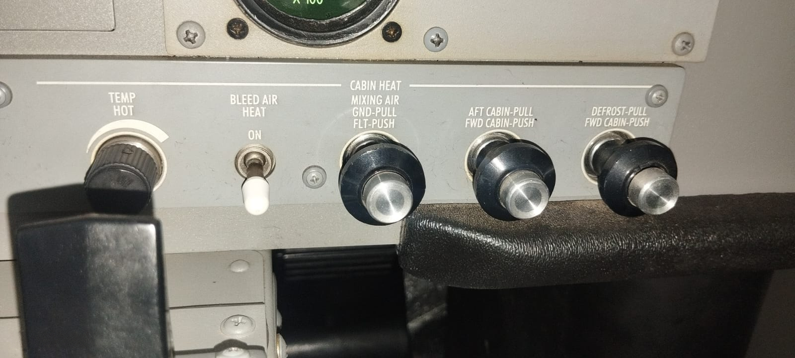
Open the full-size Caravan panel photograph ↗
Choose a control in the photograph
Start with TEMP, then follow the heat switch, mixing control and two air-destination selectors. Keyboard users can use Tab and Enter or Space.
Example installed panel. Match the aircraft and modifications to the applicable instructions. The separate cabin-heat firewall-shutoff knob is on the lower right side of the pilot’s pedestal and is outside this photograph.
Picture guide: air conditioning and temperature measurements
Follow the refrigerant and air separately
The evaporators absorb heat from cabin air. The compressor circulates refrigerant, and the condenser releases that heat to outside air. Refrigerant stays inside its closed circuit.
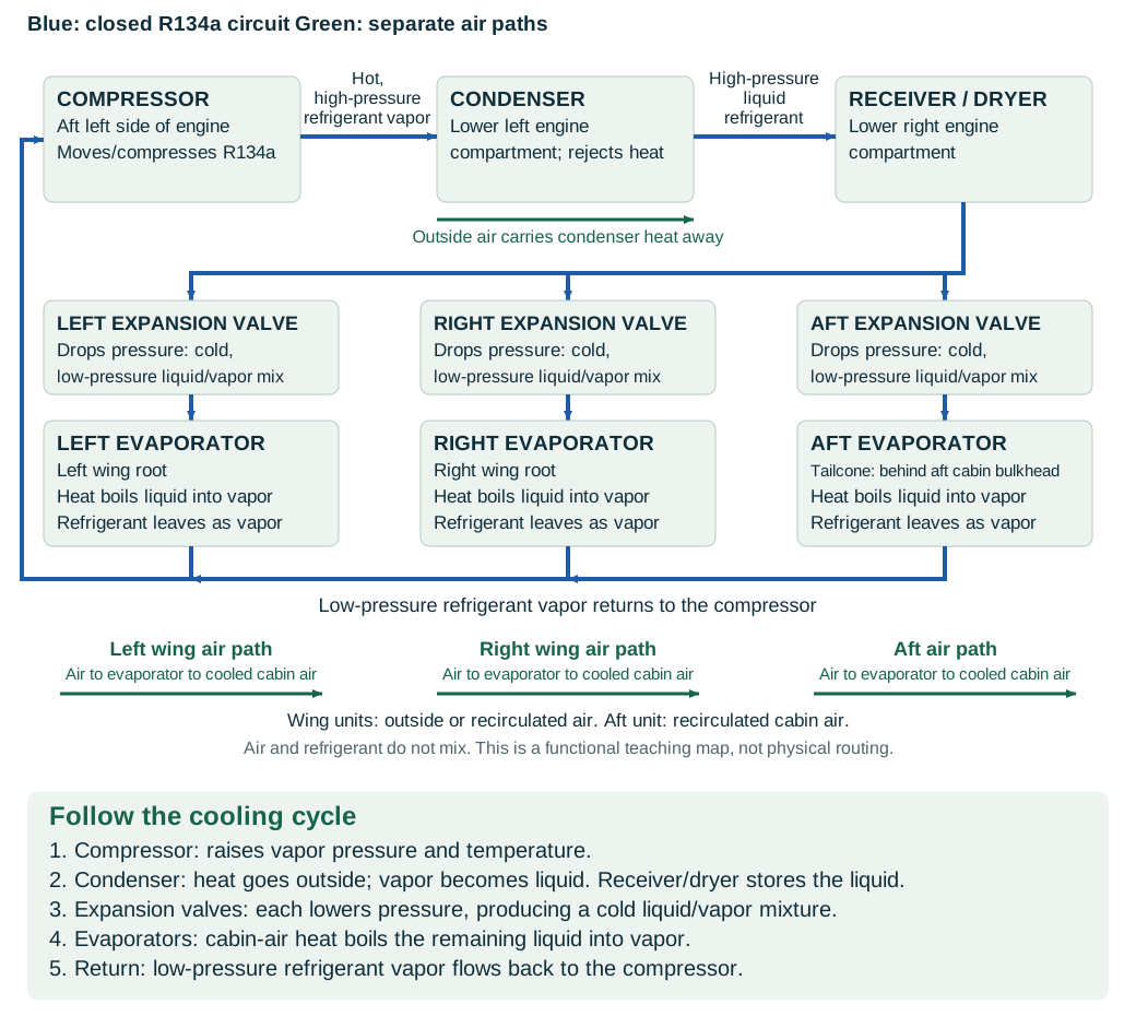
Open the full-size component diagram ↗
Know which temperature you are measuring
For the System Operational Test, outside air must be 55°F or warmer. If it is colder, postpone this cooling-performance check and repeat it under the required conditions.
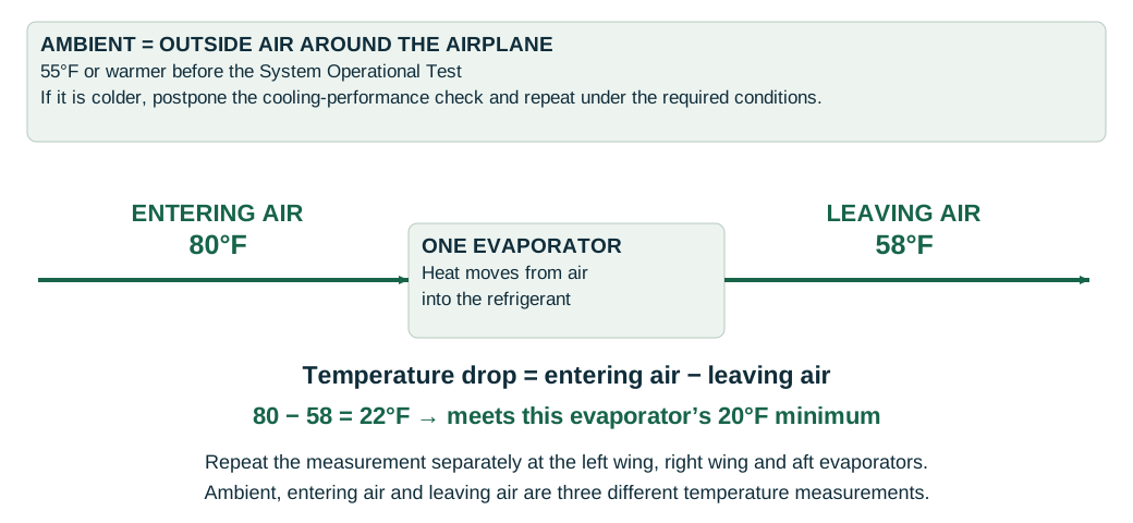
Open the full-size temperature-measurement diagram ↗
At each left-wing, right-wing and aft evaporator, subtract leaving-air temperature from entering-air temperature. Each evaporator must show at least a 20°F drop under the complete applicable test conditions.
Original functional teaching diagrams, not installation drawings. Cessna MM 21-52-00, pages 1, 4 and 220; 21-52-10, page 222. Selecting a photo label explains a control; it does not move an aircraft valve or record course completion.
Separate blower power, refrigerant heat transfer and bleed-heater flow; labeled physical connections are not one serial permission chain.
Recorded state: before the supplied change
Green outlines identify components named in the selected exercise record; they do not indicate a healthy component.
Named connections and what each arrow means
- Mode and heat controls → Refrigerant high/low pressure switchElectrical power: COOL makes clutch-control power available
- Refrigerant high/low pressure switch → Compressor and outside heat rejectionInformation / signal: Pressure permission for the clutch
- Mode and heat controls → Three evaporators and cabin-air pathsElectrical power: VENTILATE / COOL select blower power
- Compressor and outside heat rejection → Three evaporators and cabin-air pathsPhysical relationship: Liquid refrigerant to parallel metering/coil branches
- Three evaporators and cabin-air paths → Compressor and outside heat rejectionPhysical relationship: Heat-bearing vapor returns to the compressor
- Mode and heat controls → P3 heater admissionInformation / signal: Heat ON and TEMP control-pressure request
- Mixer and linked firewall doors → P3 heater admissionInformation / signal: Firewall microswitch permission
- P3 heater admission → Mixer and linked firewall doorsPhysical relationship: Metered P3 air to mixing and cabin delivery
Mode and heat controls
Request the intended function and distribute its electrical supply.
Supplied record: VENTILATE; heat OFF
How it works with the rest
OFF removes electrical power from the air-conditioning components. VENTILATE powers only the evaporator blowers. COOL starts those blowers and makes power available to the remaining cooling components. The bleed-heat ON/OFF switch and rotary TEMP control belong to the separate heater: clockwise TEMP rotation raises its pneumatic control-pressure demand.
What the evidence must show
Record COOL versus VENTILATE separately from the heat switch, TEMP selection and observed blower response.
Selected: Mode and heat controls
Follow the change through the system.
Fictional R134a trainer record: VENTILATE is selected and all three evaporator blowers run. The engine accessory drive is running and turning; clutch hardware, pressure permission, refrigerant metering, condenser airflow and cabin-air routes are serviceable. The supplied comparison changes only the air-conditioning selector to COOL; heating stays OFF. No cooling-performance measurement is supplied.
Before the recorded change
VENTILATE: left, right and aft blowers run; compressor clutch is disengaged.
Next observation
Choose your prediction before revealing the supplied result.
Reference: D2078 Rev 42 compilation: 21-52-00 pp.1,4, printed Oct 15/1999; actual PDF686,689.
Course applicability and study references
Formative supplement to TM-024 Rev D. Cooling uses the supplied D2078 Revision 42 compilation, 21-52-00 R134a description for 20800274 and on / 208B0655 and on. Heating uses 21-41-00's later arrangement: 20800180 and on, 208B0210 and on, or CAB90-9. These fictional trainer records provide qualitative states, not servicing instructions, performance limits or an aircraft release. Existing labs, records, exams and completion requirements remain separate.
- Supplied Caravan R134a description
Cessna Model 208 maintenance manual D2078-42-13, supplied Revision 42 compilation. 21-52-00 pp.1,4 (actual PDF686,689): modes, pressure protection, shared refrigeration, parallel evaporators and cabin-air routes. These description pages are dated Oct 15/1999; no claim that the compilation is a current aircraft instruction.
- Supplied later Caravan heater
Same supplied manual, 21-41-00 pp.4-5 (actual PDF619-620), dated Aug 1/1995. Later serial/CAB90-9 branch only: control pressure, independent instrument/deice regulator, mixing selection and linked firewall isolation.
Original learning diagrams and supplied training records explain the stated relationships. Current aircraft-effective instructions and authorization govern actual maintenance.